
Integrated Machine Safety Controls
Wireless Safety Enabling Switch
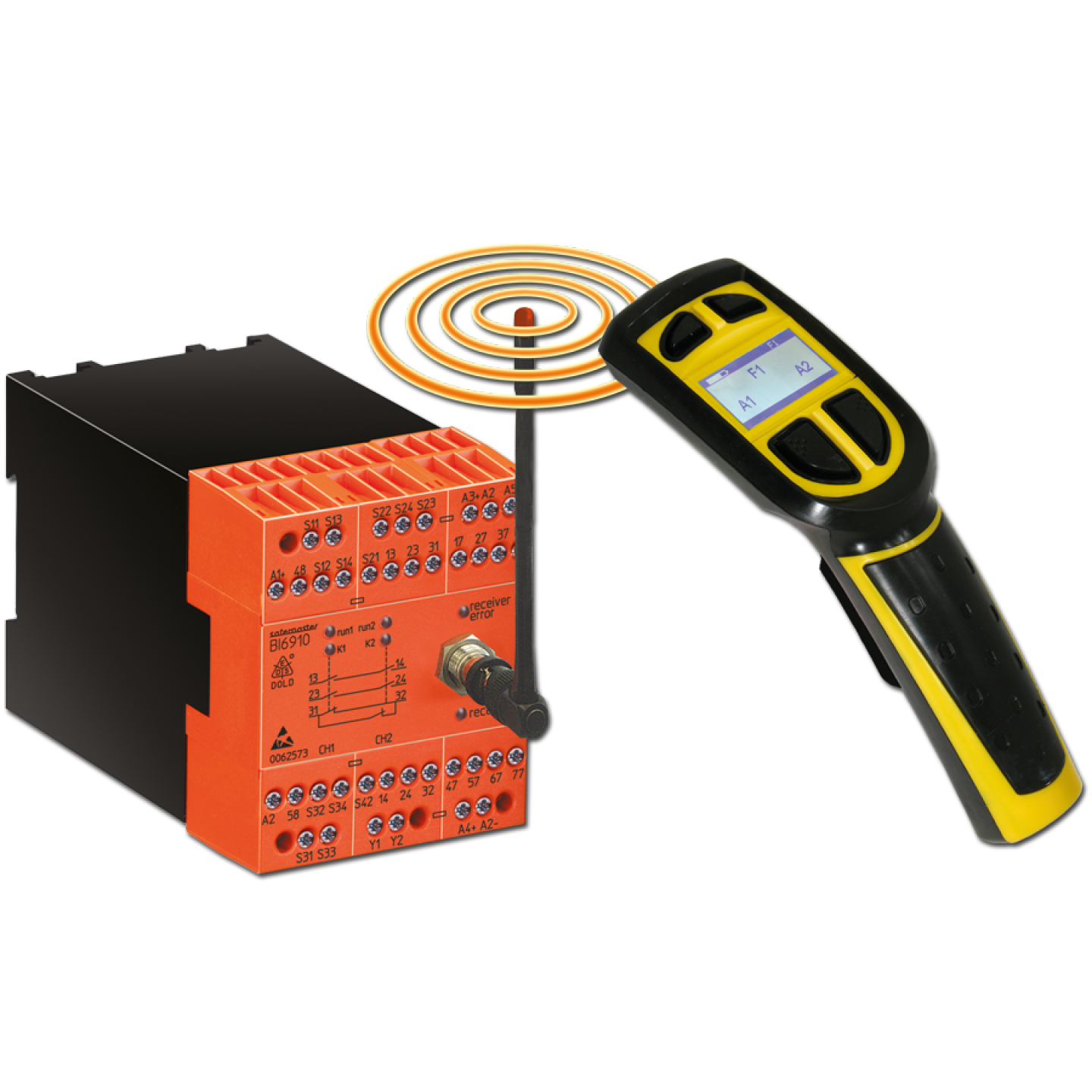
Hand-held radio enabling switch with DIN-rail safety module
The SAFEMASTER W wireless enabling system lets an operator command controlled machine movement from inside or near a safeguarded area during setup, teach, troubleshooting, and maintenance without a trailing cable or a fixed pendant station. A 340 g hand-held enabling switch (RE 6910) transmits on 433–434 MHz to a 67.5 mm DIN-rail safety module (BI 6910), which provides forcibly guided safety relay outputs plus six programmable non-safety outputs for machine functions. The system is rated to Category 4 / Performance Level e per EN ISO 13849-1 and SIL 3 per IEC/EN 61508, with a PFHd of 1.20 × 10⁻⁹ /h.
Key Features
- Category 4 / PL e per EN ISO 13849-1:2008 and SIL 3 per IEC/EN 61508 - PFHd 1.20 × 10⁻⁹ /h (wired E-stop) or 2.0 × 10⁻⁹ /h (radio E-stop), MTTFd > 100 years, SFF 99.5
- Loss of radio signal forces a passive disconnection within 500 ms; radio E-stop reaction time max. 170 ms; hardwired input reaction time max. 25 ms
- Optional infrared reset (BI 6910 _/01MF9) accepts a start only when the signal arrives by radio and infrared — the operator must point the switch at the IR receiver, enforcing line of sight to the machine
- 150–200 m range in industrial environments, up to 600 m in open area; 64 selectable channels at 1 mW or 25 channels at 10 mW, license-free under ETS 300 220
- Safety outputs: 3 NO forcibly guided contacts (BI 6910.03) or 2 NO + 1 NC indicator contact (BI 6910.22), rated AC-15 3 A / 230 V and DC-13 8 A / 24 V
- Six programmable 24 V DC semiconductor outputs (100 mA continuous, short-circuit and overload protected) for machine function commands, plus two status outputs
- Hand-held unit programmable for command mode with 4 command buttons, or function mode with up to 10 functions and 2 command buttons each
- LCD display shows function assignment, transmit status, and battery charge; function labels can be uploaded as bitmaps
- Additional hardwired safety input on the module accepts a 2-channel E-stop, safety gate, or Type 4 light curtain per EN 61496, with wire-break and short-circuit monitoring
- Feedback circuit (Y1/Y2) for monitoring external contactors; rotary step switches set manual vs. automatic start and gate-bypass behavior with the enabling switch active
- Li-ion battery delivers 40 h at 50% duty; 10 minutes of charging returns approx. 1 hour of operation; full charge in 2 h 30 min
- IP 54 ABS hand-held enclosure, −20 °C to +50 °C; module mounts on DIN rail with removable terminal blocks for fast replacement
Wireless Safety Enabling Switch
Hand-held radio enabling switch with DIN-rail safety module
The SAFEMASTER W wireless enabling system lets an operator command controlled machine movement from inside or near a safeguarded area during setup, teach, troubleshooting, and maintenance without a trailing cable or a fixed pendant station. A 340 g hand-held enabling switch (RE 6910) transmits on 433–434 MHz to a 67.5 mm DIN-rail safety module (BI 6910), which provides forcibly guided safety relay outputs plus six programmable non-safety outputs for machine functions. The system is rated to Category 4 / Performance Level e per EN ISO 13849-1 and SIL 3 per IEC/EN 61508, with a PFHd of 1.20 × 10⁻⁹ /h.
Key Features
- Category 4 / PL e per EN ISO 13849-1:2008 and SIL 3 per IEC/EN 61508 - PFHd 1.20 × 10⁻⁹ /h (wired E-stop) or 2.0 × 10⁻⁹ /h (radio E-stop), MTTFd > 100 years, SFF 99.5
- Loss of radio signal forces a passive disconnection within 500 ms; radio E-stop reaction time max. 170 ms; hardwired input reaction time max. 25 ms
- Optional infrared reset (BI 6910 _/01MF9) accepts a start only when the signal arrives by radio and infrared — the operator must point the switch at the IR receiver, enforcing line of sight to the machine
- 150–200 m range in industrial environments, up to 600 m in open area; 64 selectable channels at 1 mW or 25 channels at 10 mW, license-free under ETS 300 220
- Safety outputs: 3 NO forcibly guided contacts (BI 6910.03) or 2 NO + 1 NC indicator contact (BI 6910.22), rated AC-15 3 A / 230 V and DC-13 8 A / 24 V
- Six programmable 24 V DC semiconductor outputs (100 mA continuous, short-circuit and overload protected) for machine function commands, plus two status outputs
- Hand-held unit programmable for command mode with 4 command buttons, or function mode with up to 10 functions and 2 command buttons each
- LCD display shows function assignment, transmit status, and battery charge; function labels can be uploaded as bitmaps
- Additional hardwired safety input on the module accepts a 2-channel E-stop, safety gate, or Type 4 light curtain per EN 61496, with wire-break and short-circuit monitoring
- Feedback circuit (Y1/Y2) for monitoring external contactors; rotary step switches set manual vs. automatic start and gate-bypass behavior with the enabling switch active
- Li-ion battery delivers 40 h at 50% duty; 10 minutes of charging returns approx. 1 hour of operation; full charge in 2 h 30 min
- IP 54 ABS hand-held enclosure, −20 °C to +50 °C; module mounts on DIN rail with removable terminal blocks for fast replacement
Assembly/What's Included
A typical PowerSafe wireless enabling system includes:
- Wireless hand-held enabling switch
- 3-position enabling control
- Operator display
- Programmable function buttons
- Wireless safety receiver/module
- Safety-rated outputs for machine integration
- Radio and/or infrared communication
- Configurable control functions
- Machine-specific electrical integration
Systems are configured to the machine. Contact PowerSafe for pricing and configuration.
Required Interface Accessories
The radio link runs through a ¼ λ or ½ λ antenna that mounts directly on the front of the BI 6910. If the module is installed in a metal enclosure, the antenna must be mounted outside the cabinet and connected with DOLD coax extension (RE 5910/042, 2 m, or RE 5910/043, 5 m). Systems using the infrared reset function also require the RE 5910/060 infrared receiver with 10 m lead.
Enabling Function
| Switch Position | Machine State |
| Released | No movement enabled |
| Center (held) | Controlled movement permitted |
| Fully depressed (panic) | Safe State commanded; outputs drop out |
Output Options
- Safety outputs: forcibly guided relay contacts, 3 NO or 2 NO + 1 NC (NC is an indicator contact only, not a safety contact)
- Thermal current 5 A; AC-15 rating 3 A / 230 V (NO), 2 A / 230 V (NC); DC-13 rating 8 A / 24 V at 0.1 Hz
- Max. fuse rating 6 A gL; electrical life 100,000 cycles at 2 A / 230 V AC-15; mechanical life 10 × 10⁶ cycles
- Six transistor outputs (terminals 17, 27, 37, 47, 57, 67, 77) at 24 V DC, min. 23 V at UN, 100 mA continuous, 400 mA for 0.5 s, with internal short-circuit, over-temperature, and overload protection
- Two semiconductor status outputs (terminals 48, 58)
Timing
- Operating time: max. 1000 ms on automatic start, max. 110 ms on manual start, max. 70 ms on automatic restart
- Switch-off (reaction) time on hardwired inputs: max. 25 ms
- E-stop via radio: max. 170 ms
- Passive disconnection on interrupted radio signal: max. 500 ms
- Disconnection with active radio signal and closed charger control contact: adjustable 5–30 s
Environmental Rating
| RE 6910 (hand-held) | BI 6910 (module) | |
| Protection | IP 54 | IP 40 housing / IP 20 terminals — must be mounted in an IP 54 control cabinet per EN 61496-1 |
| Operating temp. | −20 °C to +50 °C | 0 °C to +50 °C |
| Storage temp. | −20 °C to +45 °C | −25 °C to +85 °C |
| Material | ABS | Thermoplastic, V0 per UL 94 |
| Weight | 340 g with battery | 495 g |
Technical Documentation
Enabling switch will not link to the safety module
Operator presses enable and nothing happens; reception LED on the BI 6910 stays off
- Confirm the enabling switch and module are set to the same frequency channel - the channel is selected on the enabling switch, not the module
- Verify the module has 24 V DC supply within 0.85–1.15 UN with no more than 5% residual ripple
- Check the LCD display on the hand-held unit for battery charge state; recharge if low
- Confirm the antenna is connected to the BNC fitting on the front of the module and is not loose
- If the module is in a metal cabinet, verify the antenna has been relocated outside the enclosure with a DOLD coax extension - an internal antenna will not transmit reliably
- Check the red receiver-error LED; if lit, the fault is in the radio receiver rather than the link
Machine will not start or reset
Enable switch is held at center but safety outputs will not close
- Confirm which start mode the rotary step switches are set to - manual start, automatic start, or start on removal from charger
- On BI 6910 _/01MF9 units, the reset is only accepted when the signal arrives by both radio and infrared; the operator must point the enabling switch directly at the IR receiver
- On BI 6910 _/00MF9 units, start is only possible from the hardwired start button - this is by design, not a fault
- Verify no other device in the hardwired safety input is open (E-stop, gate switch, light curtain)
- Check the Y1/Y2 feedback circuit - a welded or stuck external contactor will block the reset
- Confirm the enabling switch has been returned fully to the released position before re-enabling
Intermittent dropouts during operation
Movement stops unexpectedly while the enable switch is still held at center
- Expect a disconnection within 500 ms of any radio signal loss - this is the passive disconnection function working as designed
- Verify the operator is within the rated 150–200 m industrial range and has not moved behind heavy structure or into a shielded area
- Check for interference from VFDs, welders, or other 433 MHz equipment on adjacent machines
- Reassign the channel - the enabling switch supports fast frequency change across 64 channels
- Measure battery charge under load; a battery near end of life can drop out mid-transmission even when it reads charged at rest
- Consider the ½ λ antenna (RE 5910/041) or a 90° adapter for better placement if dropouts correlate with operator position
Unexpected shutdown while the switch is in the charger
Outputs drop out shortly after the enabling switch is returned to the charger
- This is the charger control contact function - with an active radio signal and a closed charger contact, the module disconnects after an adjustable 5–30 s delay
- Verify the charger monitoring contacts are wired to S31-S32 and S33-S34 as required by the selected operating mode
- If the delay is too short for the application, adjust the setting rather than disabling the function
Wire-break or short-circuit fault indicated
Error LED active; module will not enable
- The module monitors its control wiring for broken wires and short circuits - inspect the hardwired E-stop, gate, and light curtain loops first
- Verify input signal levels: active signals must not exceed DC 16 V, inactive signals must be below DC 9 V, and no input may exceed DC 30 V
- Check the time difference between the two channels of a single function - E-stop and light curtain inputs allow 250 ms, gate inputs allow 3 s; exceeding this registers as a fault
- Verify terminal torque and that removable terminal blocks are fully seated after any module swap
Battery will not charge or holds a short charge
Run time well below the rated 40 h, or charge fails to complete
- Confirm the charger is operating between 0 °C and +35 °C - charging outside this range damages the battery
- Check cycle count; the battery is rated for a minimum of 500 charge/discharge cycles and is a consumable
- Verify the unit is seated correctly in the charger contacts
- Replace with RE 6910/051 rather than attempting to service the pack
Physical and environmental damage
Erratic behavior after a drop, impact, or exposure
- Inspect the ABS enclosure for cracks - the hand-held unit is rated IP 54 and loses that rating once the housing is compromised
- Clean the infrared window; contamination will cause reset failures on IR-equipped systems
- Verify the three-position enable element returns cleanly from panic to released with no binding
- Confirm the module is still inside an IP 54 cabinet as required by EN 61496-1 - the module housing itself is only IP 40