Presence Sensing Safety Devices
Safety Light Curtains - Keyence GL-R Series
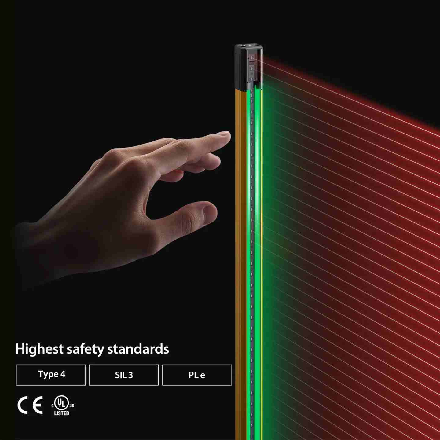
Type 4 / SIL 3 / PLe | Three detection resolutions (14 mm, 25 mm, 45 mm) | Up to 15 m range
The Keyence GL-R Series creates an infrared detection field across the full length of its housing — with no dead zones at the top or bottom — that triggers an immediate machine stop when interrupted. It's built for industrial environments where nuisance trips, wiring complexity, and lens damage from impact or washdown are real problems. Available in three sub-series (GL-RF, GL-RH, GL-RL) covering detection capabilities from ø14 mm finger detection to ø45 mm body/presence detection, with detection heights from 5.51" to 74.80" and sensing ranges up to 49.21 ft (15 m).
Key Features
- Type 4 / SIL 3 / PLe / Category 4 — highest machine safety classification; certified to IEC 61496-1/2, IEC 61508, EN ISO 13849-1:2008, UL 61496-1/2, and UL 508.
- Three detection resolutions — GL-RF: ø0.55" (14 mm) finger detection, 10 mm beam pitch, up to 32.81 ft range; GL-RH: ø0.98" (25 mm) hand detection, 20 mm beam pitch, up to 49.21 ft range; GL-RL: ø1.77" (45 mm) body/presence detection, 40 mm beam pitch, up to 49.21 ft range.
- Edge-to-edge protection with no dead zones — beams extend to within 0.39" (10 mm) of the unit ends, enabling flush mounting inside guard openings without supplemental guarding.
- IP65/IP67 enclosure rating (IEC 60529) — water-jet and watertight-rated housing; suitable for washdown environments without additional protective covers.
- 3 mm thick extruded aluminum housing with recessed lens — lens surface exposure of only 0.35" (9 mm) blocks impact from tools or parts ø0.67" (17 mm) or larger; no U-channel guarding required.
- Built-in series connection — up to 3 GL-R units connectable in series and operated as a single light curtain; OSSD response time is summed and adjusted per published formula.
- Dual OSSD safety outputs — PNP or NPN (determined by cable selection); 500 mA max load current; self-diagnostics periodically test output circuit integrity.
- Built-in EDM (External Device Monitoring) — monitors welded contacts or failed external switching devices; enables Category 4 compliance when connected to safety relays, contactors, or safety PLCs.
- 24 VDC ±20% supply, Class 2 — response time 6.6–26.8 ms (wire/optical sync, Ch. 0); Keyence GL-T11R dedicated Type 4 safety relay and SL-U2 power supply available as matched accessories.
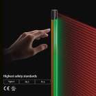
Safety Light Curtains - Keyence GL-R Series
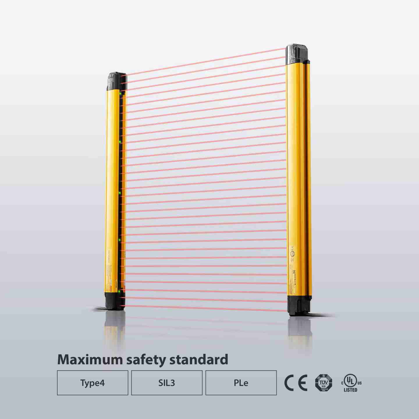
Type 4 / SIL 3 / PLe | Three detection resolutions (14 mm, 25 mm, 45 mm) | Up to 15 m range
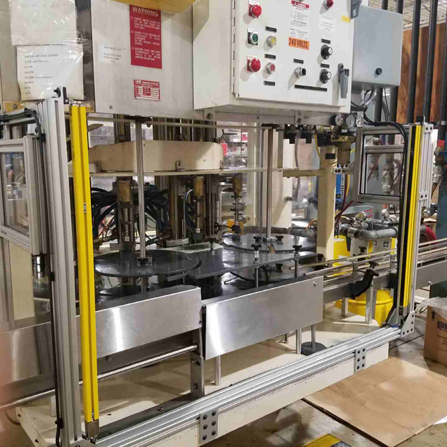
The Keyence GL-R Series creates an infrared detection field across the full length of its housing — with no dead zones at the top or bottom — that triggers an immediate machine stop when interrupted. It's built for industrial environments where nuisance trips, wiring complexity, and lens damage from impact or washdown are real problems. Available in three sub-series (GL-RF, GL-RH, GL-RL) covering detection capabilities from ø14 mm finger detection to ø45 mm body/presence detection, with detection heights from 5.51" to 74.80" and sensing ranges up to 49.21 ft (15 m).
Key Features
- Type 4 / SIL 3 / PLe / Category 4 — highest machine safety classification; certified to IEC 61496-1/2, IEC 61508, EN ISO 13849-1:2008, UL 61496-1/2, and UL 508.
- Three detection resolutions — GL-RF: ø0.55" (14 mm) finger detection, 10 mm beam pitch, up to 32.81 ft range; GL-RH: ø0.98" (25 mm) hand detection, 20 mm beam pitch, up to 49.21 ft range; GL-RL: ø1.77" (45 mm) body/presence detection, 40 mm beam pitch, up to 49.21 ft range.
- Edge-to-edge protection with no dead zones — beams extend to within 0.39" (10 mm) of the unit ends, enabling flush mounting inside guard openings without supplemental guarding.
- IP65/IP67 enclosure rating (IEC 60529) — water-jet and watertight-rated housing; suitable for washdown environments without additional protective covers.
- 3 mm thick extruded aluminum housing with recessed lens — lens surface exposure of only 0.35" (9 mm) blocks impact from tools or parts ø0.67" (17 mm) or larger; no U-channel guarding required.
- Built-in series connection — up to 3 GL-R units connectable in series and operated as a single light curtain; OSSD response time is summed and adjusted per published formula.
- Dual OSSD safety outputs — PNP or NPN (determined by cable selection); 500 mA max load current; self-diagnostics periodically test output circuit integrity.
- Built-in EDM (External Device Monitoring) — monitors welded contacts or failed external switching devices; enables Category 4 compliance when connected to safety relays, contactors, or safety PLCs.
- 24 VDC ±20% supply, Class 2 — response time 6.6–26.8 ms (wire/optical sync, Ch. 0); Keyence GL-T11R dedicated Type 4 safety relay and SL-U2 power supply available as matched accessories.
- Assembly:
- includes a matched transmitter and receiver pair
- mounting brackets and hardware for installation around the guard opening
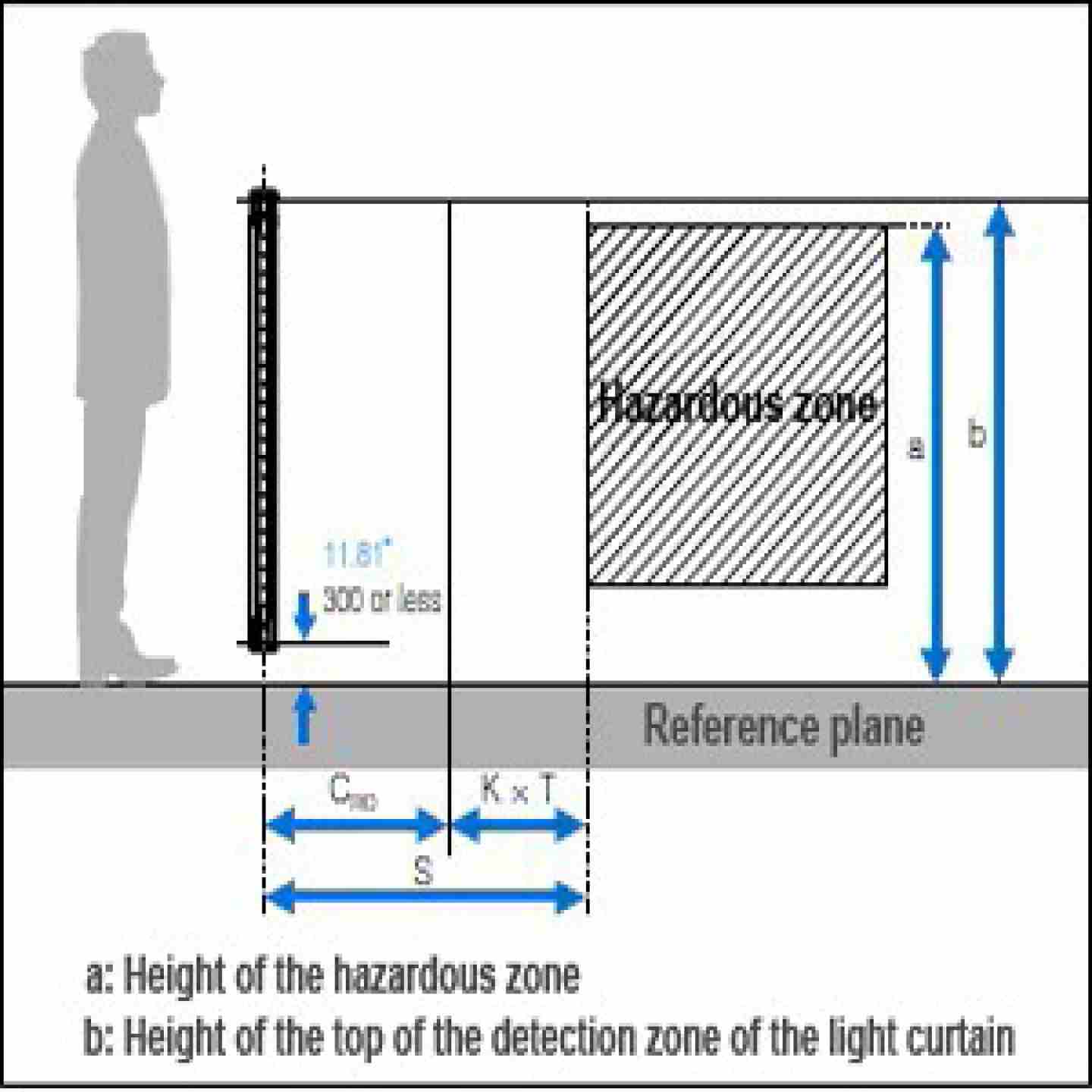
- Quick-reference guide covering alignment, wiring diagrams for the safety outputs, and recommended safety distances.
- Not Included, but required for full system compliance:
- Safety relay or safety controller
- Machine wiring cables
- Any additional interlock devices
- Output Options
- OSSD: 2 transistor outputs, PNP or NPN (cable-determined); 500 mA max (350 mA max at 122–131°F / 50–55°C); residual voltage ≤2.5 V ON, ≤2.0 V OFF; leakage ≤200 µA; max capacitive load 2.2 µF
- AUX (non-safety): transistor output, compatible with PNP and NPN; 50 mA max
- Error output: 50 mA max
- Muting lamp output: supports incandescent (24 VDC, 1–5.5 W) and LED (10–230 mA)
- Environmental Ratings
- Enclosure: IP65 (water-jet) / IP67 (watertight) per IEC 60529
- Ambient temperature (operating): 14–131°F (−10 to +55°C), no freezing
- Storage: −13 to +140°F (−25 to +60°C)
- Relative humidity: 15–85% RH, no condensation
- Ambient light: incandescent ≤3,000 lx; sunlight ≤20,000 lx
- Vibration: 10–55 Hz, 0.03" (0.7 mm) compound amplitude, 20 sweeps each axis
- Shock: 100 m/s² (≈10 G), 16 ms pulse, 1,000 times per axis
- Overvoltage category: II
- Applicable Safety Standards
- IEC 61496-1, EN 61496-, UL 61496-1
- IEC 61508 / EN 61508 (SIL 3)
- EMI: EN 55011 Class A, FCC Part 15B Class A, ICES-003 Class A
- IEC61496-1, EN61496-1, UL61496-1 (Type 4 ESPE)
- IEC61496-2, EN61496-2, UL61496-2 (Type 4 AOPD)
- IEC61508, EN61508 (SIL3)
- EN ISO13849-1:2008 (Category 4, PLe)
- UL 508
- UL 1998
~~~Download the Tech Doc - NEED TO ADD~~~
OSSD Outputs Not Turning ON After Power-Up
Light curtain powers up but OSSD remains in OFF state; machine does not enable
- Confirm both transmitter and receiver are powered at 24 VDC ±20% with ≤10% ripple (P-P). Voltage outside this range prevents normal operation.
- Verify the transmitter and receiver are a matched GL-R pair and that beam axes are oriented facing each other across the detection zone.
- Check center indicators on the receiver: if upper or lower indicators are red, those beam axes are blocked or misaligned. Use the 3-step indicator alignment process (top → bottom → rotational fine-tune) before assuming a wiring fault.
- If using the One-Line System, confirm the transmitter is connected to the receiver via the series connection cable — only the receiver requires the main wiring cable. Total cable length must not exceed 98.43 ft (30 m).
- If using Wire Synchronization, confirm Synchronization 1 (RS-485+, orange) and Synchronization 2 (RS-485−, orange/black) wires are connected between transmitter and receiver. If these wires are disconnected, the unit defaults to Optical Synchronization and transmitter I/O becomes unavailable.
- Confirm OSSD1 (black) and OSSD2 (white) are both wired to the safety control circuit — using only one OSSD output will prevent a Category 4 system and may cause the safety controller to reject the device.
- If EDM function is enabled and external devices (contactors, relays) are not feeding the correct feedback signal to the EDM input within the required window, OSSD will not turn ON. Verify EDM wiring per the wiring diagram for your cable type (requires 11-core cable on receiver).
Nuisance Trips / OSSD Cycling OFF Unexpectedly
Machine stops with no visible obstruction in the detection zone; curtain clears but trips again intermittently
- Check ambient light levels at the receiver lens. Incandescent sources above 3,000 lx or direct sunlight above 20,000 lx can cause interference. Reposition or shield the curtain accordingly.
- Inspect the lens surface for contamination — oil mist, coolant, and dust on the recessed lens reduce received light intensity. Clean with a dry lint-free cloth; do not use solvents. If using a washdown environment, confirm no water intrusion has occurred inside the connector area.
- Check for mutual interference if two GL-R systems are installed in proximity. Use the channel configuration setting switch (Channel A or B) to assign different channels to each system. Channel 0 (default) does not prevent inter-system interference.
- Verify that all mounting brackets are secure and not allowing vibration to shift alignment. For units ≥50.39" (1280 mm), confirm anti-vibration brackets are installed at the unit midpoint.
- Connect the GL-R1UB interface unit and review beam-by-beam light intensity via the PC monitoring software. Beams near the intensity threshold will appear significantly lower than others and identify the likely cause — poor alignment, contamination, or reflections.
- If using corner mirrors, confirm that each mirror in the path reduces detection range by ~10% and that the actual working distance remains within specification after all mirrors are accounted for.
- Review whether Fixed Blanking or Reduced Resolution is applied. These are intentional protection zone reductions — if a previously-masked area is now being monitored (e.g., after a configuration change), that is expected behavior, not a fault.
Error Condition (Center Indicator Flashing Red)
7-segment display shows an error code; OSSD is in OFF state; curtain does not clear after removing obstruction
- Record the 7-segment display error code on the receiver and cross-reference it with the GL-R Instruction Manual error table. Each code maps to a specific internal fault (e.g., output circuit failure, synchronization loss, EDM fault).
- For synchronization errors (optical sync mode): verify there are no obstructions or strong reflective surfaces between transmitter and receiver. The "All Blocked" condition in optical sync mode triggers an extended response time as the unit re-synchronizes — this is normal behavior, not a permanent fault.
- For OSSD internal circuit errors: the GL-R performs self-diagnostics that periodically force the OSSD into a brief OFF state. A sustained error here indicates a genuine output circuit failure — replace the unit.
- If the error appeared after a wiring change, disconnect power, re-inspect all connections against the appropriate wiring diagram (5-core, 7-core, or 11-core per your wiring system), then re-power. Miswiring the Muting, Override, or Interlock inputs can trigger error states.
- For Interlock condition (yellow INTERLOCK indicator ON): the OSSD will not turn ON automatically after clearing. Press the reset input switch to release the interlock. If no reset switch is wired, confirm Interlock is intentionally enabled via the setting switch or software — if not, disable it.
- For cascaded (series-connected) installations: isolate which unit in the series is faulted by disconnecting the series connection cables one at a time. A fault in one unit causes the entire series to drop into the OFF state.
Alignment Failures After Installation or Relocation
Indicators show correct alignment during installation but unit trips shortly after; or curtain cannot reach a fully green (clear) state
- Use the GL-R1LP battery-operated laser alignment tool before powering the system. Attach it to the transmitter end and verify the laser points at the corresponding receiver position across the full curtain length, not just the top and bottom.
- Follow the 3-step indicator alignment sequence: (1) rotate transmitter until the top-center indicator on the receiver turns red — top beam axis is aligned; (2) continue until bottom indicator turns red — bottom beam axis is aligned; (3) fine-tune rotational position until all indicators change to green.
- After mechanical alignment, use the GL-R1UB interface unit and PC software to view per-beam intensity. An installation that appears aligned visually may still have beams near the minimum threshold — the software will show this before it causes nuisance trips in production.
- For units ≥50.39" (1280 mm), check for flex or bow in the mounting structure. Long curtains are sensitive to frame deflection. Anti-vibration brackets at the midpoint are required; verify they are installed and that the frame itself is rigid.
- If using GL-RB01 or GL-RB02 adjustable angle brackets, confirm screws are fully tightened in the selected position after adjustment. These brackets allow 180° of angular adjustment — partial tightening allows post-installation drift.
Preventive Maintenance
Perform the following checks at each scheduled maintenance interval (minimum quarterly, or per the site's safety inspection schedule):
- Clean lens surfaces on both transmitter and receiver with a dry, lint-free cloth. In coolant or oil mist environments, inspect after each production run.
- Inspect all cable connections and connectors for corrosion, loosening, or damage. M12 and M14 connectors must be fully seated and finger-tight.
- Verify mounting bracket screws and anti-vibration brackets are secure. Retighten to the manufacturer-specified torque if any movement is detected.
- Perform a full functional test using the correct test piece for the curtain type: ø0.55" (14 mm) for GL-RF, ø0.98" (25 mm) for GL-RH, ø1.77" (45 mm) for GL-RL. Pass the test piece through the detection zone at multiple points along the curtain height and confirm the machine stops as expected each time.
- If the GL-T11R safety relay is used, verify relay contact life has not been exceeded (electrical life: 100,000 cycles at 250 VAC 6 A). Replace the relay board (OP-87682) if near or past rated cycle count — this can be done without removing wiring.
- Document all test results and inspection dates in the machine safety log.
Fault Tracking
Keep a log of each OSSD trip event that includes: date/time, 7-segment error code (if present), which beam axes were affected (from indicator state), environmental conditions at the time (recent cleaning, ambient light changes, nearby equipment operation), and resolution action taken. Patterns in the log — such as trips occurring consistently after washdown or at specific times of day — typically point to contamination, thermal expansion of mounting structures, or light interference from other equipment, rather than device failure.