Presence Sensing Safety Devices
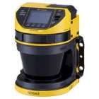
Safety Laser Scanners - Keyence SZ-V Series
Type 3 | SIL 2 | Category 3 | PLd — Integrated and Separate System Configurations
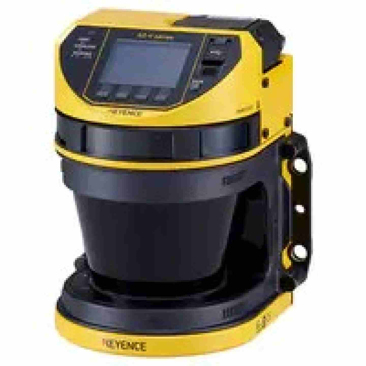
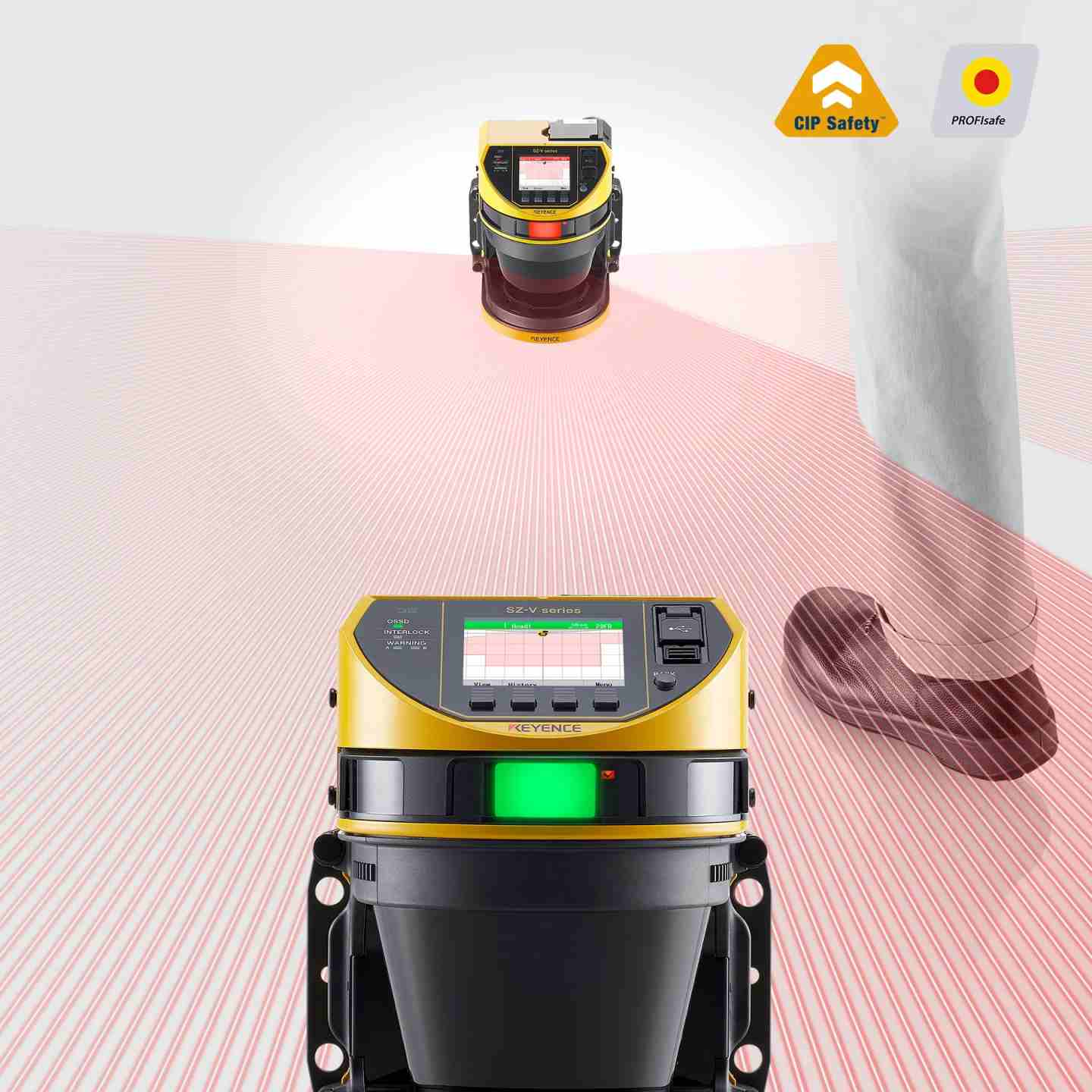
The Keyence SZ-V Series safety laser scanner uses time-of-flight detection to create a configurable 2D protection field across a 190° field of view, stopping hazardous machine motion whenever a person or object enters the zone.
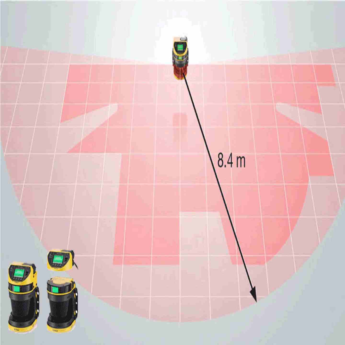
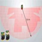
With a maximum protection zone reach of 8.4 m (27.56') and a warning zone of up to 26 m (85.30'), a single unit can replace multiple scanners in applications where conventional equipment would require corner-mounted pairs. Rated Type 3 / SIL 2 / PLd / Category 3, it is suited for area protection around robotic cells, access guarding at production line inlets, and collision avoidance on automated guided vehicles (AGVs/AGCs).
Key Features
- Type 3 / SIL 2 / PLd / Category 3 safety rating — maximum safety classification for laser scanners per IEC 61496-1/3, EN ISO 13849-1, and IEC 61508
- 8.4 m (27.56') protection zone at 190° field of view — with a 26 m (85.30') warning zone for pre-alert detection; covers areas that previously required 4 corner-mounted scanners with as few as 2 units
- Intensity Comparison Algorithm (I.C.A.) and 0.1° beam pitch — on-board algorithm distinguishes people and objects from airborne dust and mist to reduce nuisance trips in dirty or misting environments
- Up to 32 programmable zone banks — enables dynamic zone switching for AGV speed control and multi-position machine guarding; encoder inputs supported for smooth profile transitions
- World's first integrated dual camera (camera models) — captures images and video before and after each OSSD trip; Detection History log stores up to 500 events with time, position, duration, and OSSD/warning status
- IP65 enclosure rating — 24 VDC operation; operating range −10 to +50°C (14 to 122°F); shock-rated to 100 m/s² in X, Y, Z axes
Safety Laser Scanners - Keyence SZ-V Series
Type 3 | SIL 2 | Category 3 | PLd — Integrated and Separate System Configurations
The Keyence SZ-V Series safety laser scanner uses time-of-flight detection to create a configurable 2D protection field across a 190° field of view, stopping hazardous machine motion whenever a person or object enters the zone.
With a maximum protection zone reach of 8.4 m (27.56') and a warning zone of up to 26 m (85.30'), a single unit can replace multiple scanners in applications where conventional equipment would require corner-mounted pairs. Rated Type 3 / SIL 2 / PLd / Category 3, it is suited for area protection around robotic cells, access guarding at production line inlets, and collision avoidance on automated guided vehicles (AGVs/AGCs).
Key Features
- Type 3 / SIL 2 / PLd / Category 3 safety rating — maximum safety classification for laser scanners per IEC 61496-1/3, EN ISO 13849-1, and IEC 61508
- 8.4 m (27.56') protection zone at 190° field of view — with a 26 m (85.30') warning zone for pre-alert detection; covers areas that previously required 4 corner-mounted scanners with as few as 2 units
- Intensity Comparison Algorithm (I.C.A.) and 0.1° beam pitch — on-board algorithm distinguishes people and objects from airborne dust and mist to reduce nuisance trips in dirty or misting environments
- Up to 32 programmable zone banks — enables dynamic zone switching for AGV speed control and multi-position machine guarding; encoder inputs supported for smooth profile transitions
- World's first integrated dual camera (camera models) — captures images and video before and after each OSSD trip; Detection History log stores up to 500 events with time, position, duration, and OSSD/warning status
- IP65 enclosure rating — 24 VDC operation; operating range −10 to +50°C (14 to 122°F); shock-rated to 100 m/s² in X, Y, Z axes
- Assembly:
- Scanner main unit (Keyence SZ-V Series ).
- Mounting bracket kit and hardware for floor or wall application
- Quick-start configuration software and user guide (digital).
- Power/I/O cable (e.g., 24 VDC input, OSSD outputs) — controller/safety relay sold separately.
- Output Options
- Hardwired OSSD
- Network Safety Output
- Cascade
- Up to 3 scanner heads can be connected to a single display unit
- Environmental Rating
- IP65 (IEC 60529)
- Operating Temperature: −10 to +50°C (14 to 122°F), non-freezing
- Operating Humidity: 35–85% RH, non-condensing
- Shock: 100 m/s² (approx. 10 G), 16 ms pulse, 1,000 times per axis
- Vibration: 10–55 Hz, 0.7 mm compound amplitude, 20 sweeps per axis (X, Y, Z)
- Applicable Safety Standards
- IEC61496-1, EN61496-1, UL61496-1 (Type 3 ESPE)
- EN55011 ClassA, FCC Part15B ClassA, ICES-003 ClassA
- IEC61496-1, EN61496-1, UL61496-1 (Type 3 ESPE), IEC61496-3, EN61496-3 (Type 3 AOPDDR), IEC61508, EN61508,
EN ISO13849-1, 2015 (PLd, Category3), UL508, UL1998, CSA C22.2 No.14, CSA C22.2 No.0.8
Nuisance Trips / OSSD Cycling Off Without Visible Obstruction
Commonly caused by airborne contamination, marginal zone boundaries, or mutual interference from adjacent scanners
- Check the Detection History log on the display unit or SZ-V Configurator software. Review time, position (X,Y), and duration for each event to determine whether trips are repeating in the same location or are random.
- Use the built-in camera (camera models) to review images captured before and after each trip — identify whether the cause is a worker, dropped tool, forklift mast, or airborne particulate.
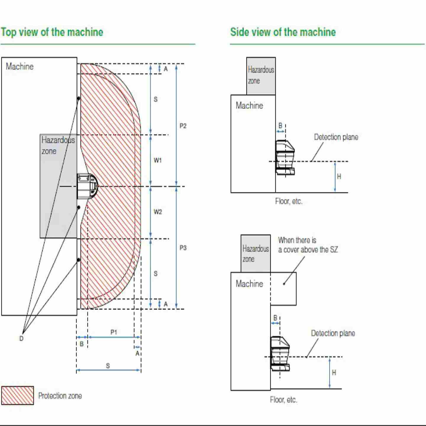
- If trips are location-specific near the zone boundary, verify that the protection zone boundary is set at least 100 mm (3.94") beyond the minimum required safety distance. If highly reflective surfaces exist within 1.5 m of the zone boundary, an additional 200 mm must be added to the safety distance calculation.
- For environments with dust, coolant mist, or smoke: confirm the Intensity Comparison Algorithm (I.C.A.) is active. The SZ-V requires several consecutive beam axes to reflect within the signal profile before registering a detection — single-axis reflection from airborne particles should not trigger an OSSD event if I.C.A. is properly configured.
- If two or more SZ-V units are operating in proximity, mutual interference between adjacent scanners can cause false trips. Verify each scanner is mounted so that their detection planes do not directly face each other, or configure appropriate scan cycle offsets.
- Confirm ambient light sources (incandescent, halogen) are rated below 1,500 lux and are not positioned within ±5° of the scanner's detection plane.
OSSD Fails to Reset After Zone Is Cleared
Commonly caused by interlock function active, EDM error, or zone not fully vacated
- Confirm whether the interlock function is enabled. If so, a manual reset input (momentary N.O. contact) must be triggered after the zone clears. Verify the reset switch wiring and that the switch is positioned so the operator can visually confirm the zone is clear before resetting.
- Check the display unit for an EDM (External Device Monitoring) error. EDM monitors the external device contacts (safety relay or contactor) to verify they are responding correctly to OSSD ON/OFF transitions. If the feedback loop is broken or the device responds too slowly, EDM will hold the OSSD off.
- Verify the protection zone is fully clear — the SZ-V detects objects as small as the configured minimum object size anywhere within the zone boundary, including at close range near the scanner head (within 100 mm additional safety distance).
- If operating in a multi-bank configuration, confirm the bank switching inputs are correctly selecting the intended zone profile. An incorrect bank selection can result in a zone that appears occupied when the actual monitored area is clear.
Scanner Fails to Power On or Display Is Blank
Commonly caused by power supply issues, cable faults, or blown protection
- Verify the supply voltage is 24 VDC ±10% at the scanner connector (not at the panel). Voltage drop across long cable runs is common; power and I/O cable must not exceed 30 m (98.43') for standard operation.
- Check all connector pins for proper seating. The standard power cable (SZ-VP series) uses a multi-pin connector; partial engagement will cause intermittent power or missing signals.
- For separate system configurations, confirm the connection cable (SZ-VS series) between the display unit and scanner head is correctly seated at both ends and is not damaged. The display unit will not initialize without a properly connected scanner head.
- If using a battery power source (AGV), verify operating voltage remains within the 24 VDC +20%/−30% range and that cable lengths to each head do not exceed 10 m when running two heads or 5 m when running three heads.
Detection Zone Not Behaving as Configured
Commonly caused by zone file mismatch, CRC code discrepancy, or bank switching logic error
- Verify the CRC (Configuration Code) shown on the display unit matches the code in the SZ-V Configurator software. A mismatch indicates the unit's active configuration does not match the approved file — this must be resolved before placing the scanner in service.
- If zones were imported via XML from third-party software (robotics system, AGV software), re-verify the zone geometry in the SZ-V Configurator after import. Coordinate origin and scaling differences between software platforms can shift zone boundaries.
- For multi-bank applications: confirm each bank switch input state corresponds to the intended zone profile. Use the Configurator monitoring view to watch the active bank number in real time while toggling inputs.
- If using the Dynamic Drawing function (field reflector method): confirm the reflectors are still in their original positions and have not been moved, covered, or damaged. Reference point monitoring will generate an alert if monitored reflectors fall outside the defined tolerance (±100 mm for access protection applications per IEC 61496-3 Annex A.12/A.13).
Window Contamination Warning or Error
Contamination of the optical window is one of the most common causes of degraded detection performance
- Inspect the polycarbonate/PEI scanner window for accumulation of dust, oil, coolant mist, or other deposits. Clean with a soft, lint-free cloth using an appropriate solvent — refer to the Keyence user manual for approved cleaning materials.
- The display unit and Configurator software will both indicate window contamination status. Respond to warning-level alerts before they escalate to error-level, which will take the scanner offline.
- If the installation environment consistently generates contamination faster than maintenance intervals allow, consider adding the SZ-VB21 protection cover or SZ-VB22 protection cover with visor to reduce direct exposure of the window. Note: protection covers can be mounted over existing mounting brackets.
- For high-contamination environments (coolant spray, grinding dust), evaluate whether the application requires supplemental physical guarding or more frequent inspection intervals and document this in your safety validation.
Network Communication Faults (CIP Safety / PROFIsafe Models)
Applies to SZ-V32NC(X) and SZ-V32N(X) in network-mode operation
- Verify Ethernet cable category (Cat5 or higher, STP or UTP), and that the cable does not exceed 100 m between the scanner and Ethernet switch.
- Confirm IP address, subnet mask, and MAC address settings on the display unit match the network configuration. These are visible directly on the display unit under the IP Setting screen.
- When using PROFIsafe: add 6 ms to the stated scanner response time when calculating your safety distance. When using CIP Safety: add 10 ms.
- Note that when PROFIsafe or CIP Safety is active, all physical I/O wires (OSSD, EDM, Reset, AUX) are deactivated — safety control must route through the network. Verify your Safety PLC is receiving the Protection Zone State bits from the correct byte offsets in the input data frame (see catalog page 22 for PROFIsafe/CIP Safety I/O mapping).
- Check the PROFINET Diagnostics alert table for specific error types (window pollution, bank input error, bank sequence error, configuration error, system error). These alerts appear in the Safety PLC and can help pinpoint the fault without physically accessing the scanner.
Preventive Maintenance
- Inspect and clean the optical window at every scheduled maintenance interval — frequency should be defined based on the contamination level of the installation environment.
- Verify the physical mounting is secure (no loosened fasteners, drift, or vibration-induced shift) at each inspection. Confirm the protection zone origin has not shifted by running a reference point check if reference point monitoring is enabled.
- Perform a full functional test after any maintenance: introduce a test object of the configured minimum detectable size into the protection zone, confirm the OSSD turns off, remove the object, reset if required, and confirm return to normal operation.
- Replace the optical window (SZ-VHW) if scratched, pitted, or unable to be cleaned to a satisfactory condition.
- When replacing a scanner unit, transfer the SZ-VSM system memory module from the old unit to the new unit to restore the approved configuration without re-programming.
Fault Tracking
- Use the Detection History feature in the SZ-V Configurator to export event logs (time, position, duration, zone state) for analysis. Up to 500 events are stored on the unit.
- For camera-equipped models, retain trip photos and video clips associated with recurring or unexplained OSSD events. These images are accessible through the Configurator software Monitoring > History view.
- Document any window contamination warnings, EDM errors, or bank input errors with timestamps. Recurring patterns indicate either an environmental issue (contamination, interference) or a wiring/configuration problem that should be resolved before the next production shift.
- Cross-reference Detection History events against production records (machine cycle, shift changes, material flow) to identify process-driven causes.