
Presence Sensing Safety Devices
RFID Safety Switches (Non-Locking) — Allen-Bradley SensaGuard
Non-contact RFID interlock switches rated to PLe / Category 4 / SIL 3 / Type 4
The 440N SensaGuard is a non-contact safety interlock switch that combines RFID coding with inductive sensing to monitor guard doors, gates, and access covers and command a machine stop the moment a guard opens. A 10–25 mm sensing range and high tolerance to misalignment reduce nuisance trips on doors that sag or shift, while unique (high) coding delivers tamper-resistant, defeat-resistant operation. Available in plastic barrel, stainless steel barrel, and flat-pack housings — all IP69K wash-down rated — and certified up to PLe / Category 4 / SIL 3 / Type 4.
Key Features
- Achieves Cat 4 / PLe per ISO 13849-1, Type 4 per ISO 14119, and SIL CL3 per IEC 61508 / IEC 60947-5-3
- Available in standard (low) or unique (high) coding — unique coding provides tamper-resistant, defeat-resistant protection per ISO 14119
- 10 mm to 25 mm sensing range (model-dependent) compensates for guard door misalignment
- Series-connectable with other SensaGuard units, light curtains, E-Stops, and key interlocks while maintaining Cat 4 / SIL 3 / PLe (8-pin models only)
- No dedicated interlock relay required — switches wire directly into the safety circuit
- IP66 / IP67 / IP69K rated for washdown, high-moisture, and harsh industrial environments
- Verified functional safety data: PFHD = 1.12 × 10⁻⁹, MTTFd > 385 years
- Housing options: plastic barrel (18 mm / 30 mm actuator), stainless steel barrel (18 mm actuator), and large plastic flat-pack — stainless steel suited to food & beverage and high-pressure washdown
- Standard, magnetic-hold, and integrated-latch versions to match different mounting profiles and access points
- Optional magnetic hold aids door stability and further reduces nuisance tripping
- On-board LED diagnostics for switch status and fault finding, with margin (approach distance) indication on select models
- M12 quick-connect pigtail in 5-pin or 8-pin configurations for fast installation
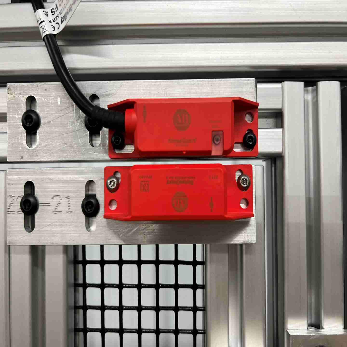
RFID Safety Switches (Non-Locking) — Allen-Bradley SensaGuard
Non-contact RFID interlock switches rated to PLe / Category 4 / SIL 3 / Type 4
The 440N SensaGuard is a non-contact safety interlock switch that combines RFID coding with inductive sensing to monitor guard doors, gates, and access covers and command a machine stop the moment a guard opens. A 10–25 mm sensing range and high tolerance to misalignment reduce nuisance trips on doors that sag or shift, while unique (high) coding delivers tamper-resistant, defeat-resistant operation. Available in plastic barrel, stainless steel barrel, and flat-pack housings — all IP69K wash-down rated — and certified up to PLe / Category 4 / SIL 3 / Type 4.
Key Features
- Achieves Cat 4 / PLe per ISO 13849-1, Type 4 per ISO 14119, and SIL CL3 per IEC 61508 / IEC 60947-5-3
- Available in standard (low) or unique (high) coding — unique coding provides tamper-resistant, defeat-resistant protection per ISO 14119
- 10 mm to 25 mm sensing range (model-dependent) compensates for guard door misalignment
- Series-connectable with other SensaGuard units, light curtains, E-Stops, and key interlocks while maintaining Cat 4 / SIL 3 / PLe (8-pin models only)
- No dedicated interlock relay required — switches wire directly into the safety circuit
- IP66 / IP67 / IP69K rated for washdown, high-moisture, and harsh industrial environments
- Verified functional safety data: PFHD = 1.12 × 10⁻⁹, MTTFd > 385 years
- Housing options: plastic barrel (18 mm / 30 mm actuator), stainless steel barrel (18 mm actuator), and large plastic flat-pack — stainless steel suited to food & beverage and high-pressure washdown
- Standard, magnetic-hold, and integrated-latch versions to match different mounting profiles and access points
- Optional magnetic hold aids door stability and further reduces nuisance tripping
- On-board LED diagnostics for switch status and fault finding, with margin (approach distance) indication on select models
- M12 quick-connect pigtail in 5-pin or 8-pin configurations for fast installation
- Assembly
- SensaGuard non-contact switch body and matched RFID actuator (standard/low or unique/high coded, per model)
- Mounting hardware for the selected housing style — plastic barrel (18 mm or 30 mm actuator), stainless steel barrel (18 mm actuator), or large plastic flat-pack
- M12 quick-connect cord set or integral cable as specified (5-pin or 8-pin; 3 m or 10 m cable options)
- Installation guide, wiring instructions, and safety data documentation
- For series/cascade wiring, Rockwell's recommended interface accessories include the safety-wired 4-port distribution box (898D-P84RT-M19), safety-wired T-port (898D-438Y-D8), and safety-wired shorting plug (898D-41KU-DM); a compatible dual-channel safety relay or safety controller is required to monitor the OSSD outputs and is sold separately.
- Output Options
- Dual-channel OSSD safety outputs; 8-pin models support series connection with full Cat 4 / SIL 3 / PLe integrity
- 5-pin quick-connect available for single-device applications
- Margin indication output on select models (order codes N / N9; N9 adds magnet) — available on the flat-pack (S2) housing only
- LED status and fault indication on-board
- Cascade Capacity
- Multiple SensaGuard switches can be connected in series on a single safety circuit while maintaining Cat 4 / SIL 3 / PLe (8-pin models only).
- Environmental Ratings
- IP66, IP67, and IP69K rated (washdown / high-pressure clean-down capable)
- Stainless steel barrel model recommended for harsh environments and food & beverage washdown zones
- Applicable Safety Standards
- IEC 60947-5-3
- IEC 61508
- ISO 14119
- ISO 13849 Cat 4/PL e/SIL 3
Actuator Detection / Sensing Issues
Switch reads "guard open" with the door closed, or won't detect the actuator
- Confirm the actuator is within the rated 10–25 mm sensing range and aligned per the misalignment curve
- Check for guard door sag, hinge wear, or mounting shift that has moved the actuator out of the sensing window
- Verify the correct actuator is paired to the switch — for unique (high) coded models, confirm the teach/learn cycle completed successfully
- Inspect the sensor and actuator faces for metal chips, coolant, or debris buildup
Coding / Teach-Cycle Faults (Unique-Coded Models)
Sensor won't recognize any actuator, or indicates a learn fault
- Ensure the actuator remained in the sensing field for the full required teach duration
- Confirm the LED sequence matched the documented teach pattern
- Verify you have not exceeded the allowed number of learn cycles for the model
- Re-run the teach process per the installation guide if a mismatch or incomplete learn is suspected
Power & Wiring Issues
Outputs won't energize, or switch fails to drop outputs on guard open
- Confirm the unit is powered at the correct 24 V DC and that supply voltage is stable (no drops under load)
- Verify OSSD output wiring is correct, secure, and free of corrosion at connectors
- Check for short-circuit faults — output shorted to 0 V, 24 V, or cross-shorted between channels will force a fault or output shutdown
- Confirm 5-pin vs. 8-pin wiring matches the application (series connection requires 8-pin)
Status / Diagnostic LED Interpretation
Unclear machine state or unexpected indicator behavior
- Solid green: safe / guard closed, outputs active
- Red: not safe / guard open
- Flashing amber-green: actuator approaching maximum sensing distance — realignment recommended
- Flashing red-green patterns: fault codes (learn failure, wrong actuator, learn count exceeded) — decode using the installation manual
- Compare indicator state against actual door condition to isolate wiring vs. sensing faults
Mechanical / Mounting Issues
Intermittent operation or drift over time
- Confirm switch and actuator are securely mounted with no movement or excessive vibration
- Verify the device is not being used as a mechanical door stop — dedicated guard stops and guides must be present
- Retighten fasteners to spec and confirm mounting hasn't shifted beyond the misalignment allowance
Series / Cascaded System Issues
One fault takes down the whole string
- Inspect each switch in the series individually to isolate the failed or miswired unit
- Confirm all cascaded units are 8-pin and wired for series operation
- Verify the safety relay or controller reading the string is correctly configured
Environmental & Contamination Factors
Degraded or inconsistent performance
- Clean inductive/RFID mating surfaces of dirt, coolant, oil splatter, and metal shavings
- Confirm the installed IP rating (IP66/67/69K) matches actual conditions — specify the stainless steel model for high-pressure washdown
- Check for external electromagnetic interference near the sensor/actuator interface
Functional Testing (After Install or Maintenance)
- Open the guard and confirm outputs drop and the machine stops
- Attempt restart with the guard open — the system must not allow operation until the guard is closed and reset (if required)
- Confirm behavior against your safety control logic and machine risk assessment
Safety Distance & Guard Design Verification
System design or audit concerns
- Use your machine risk assessment to confirm sensing range, actuator geometry, and door travel meet required safe distances per ISO 13855 / ISO 13849-1
- Verify actuator coding requirements (unique coding where anti-tamper/defeat resistance is required by risk assessment)
Preventive Maintenance
To avoid recurring issues, at regular intervals (e.g., quarterly or semi-annually depending on duty cycle):
- Inspect and clean the inductive/RFID sensing surfaces
- Check actuator and switch head for wear
- Retighten mounting hardware and confirm alignment hasn't drifted
- Validate wiring connectors for corrosion or looseness
- Perform a full functional test
Fault Tracking & Continuous Improvement
- Log every fault or trip (date, condition, LED codes)
- Look for patterns — repeated misalignment, vibration, or connector degradation
- Use the data to identify root causes and prevent recurrence