
Presence Sensing Safety Devices
RFID Safety Interlock Switches (Locking) - Keyence GS Series
Power-to-release and power-to-lock guard locking switches rated to PLe / Category 4 / SIL 3 / Type 4
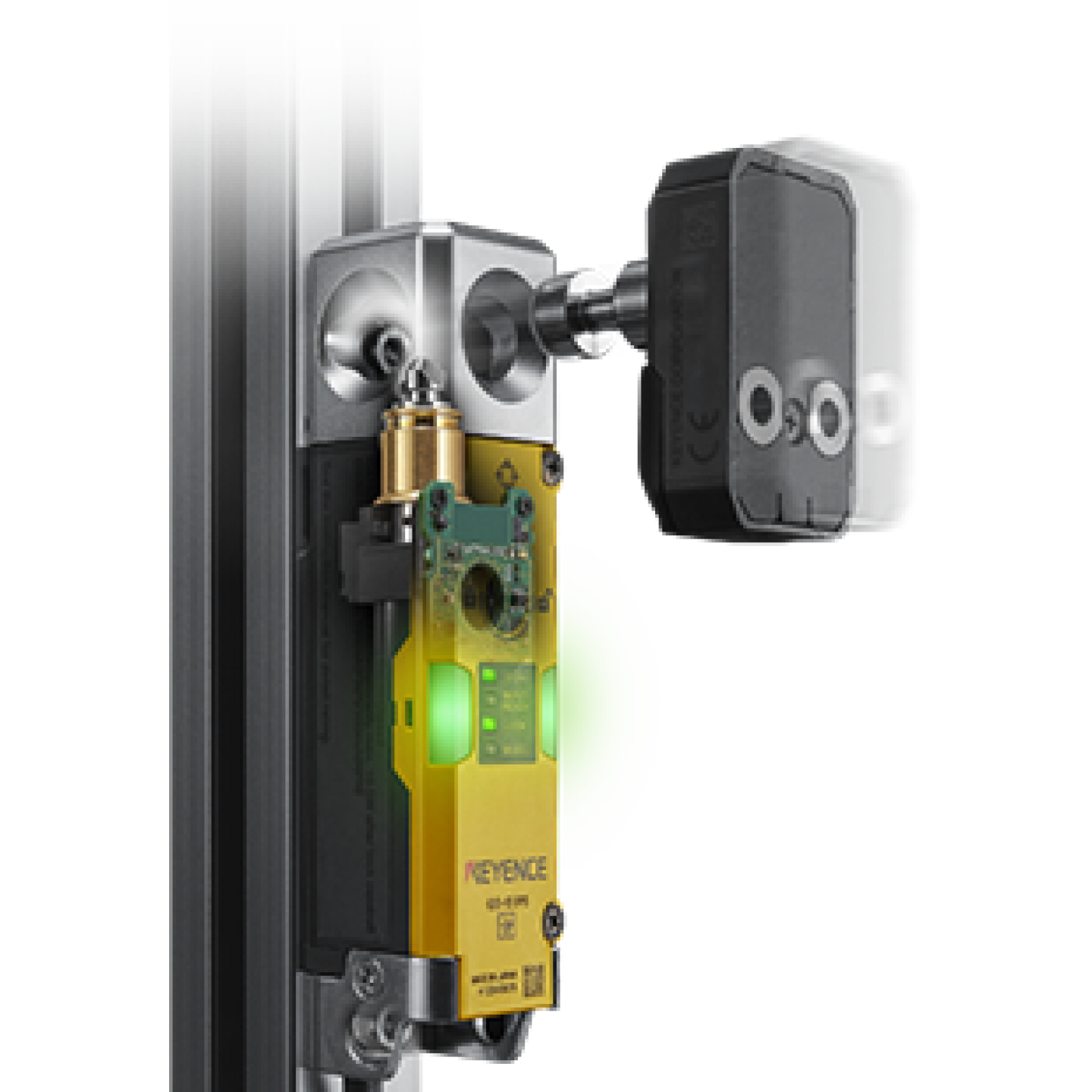
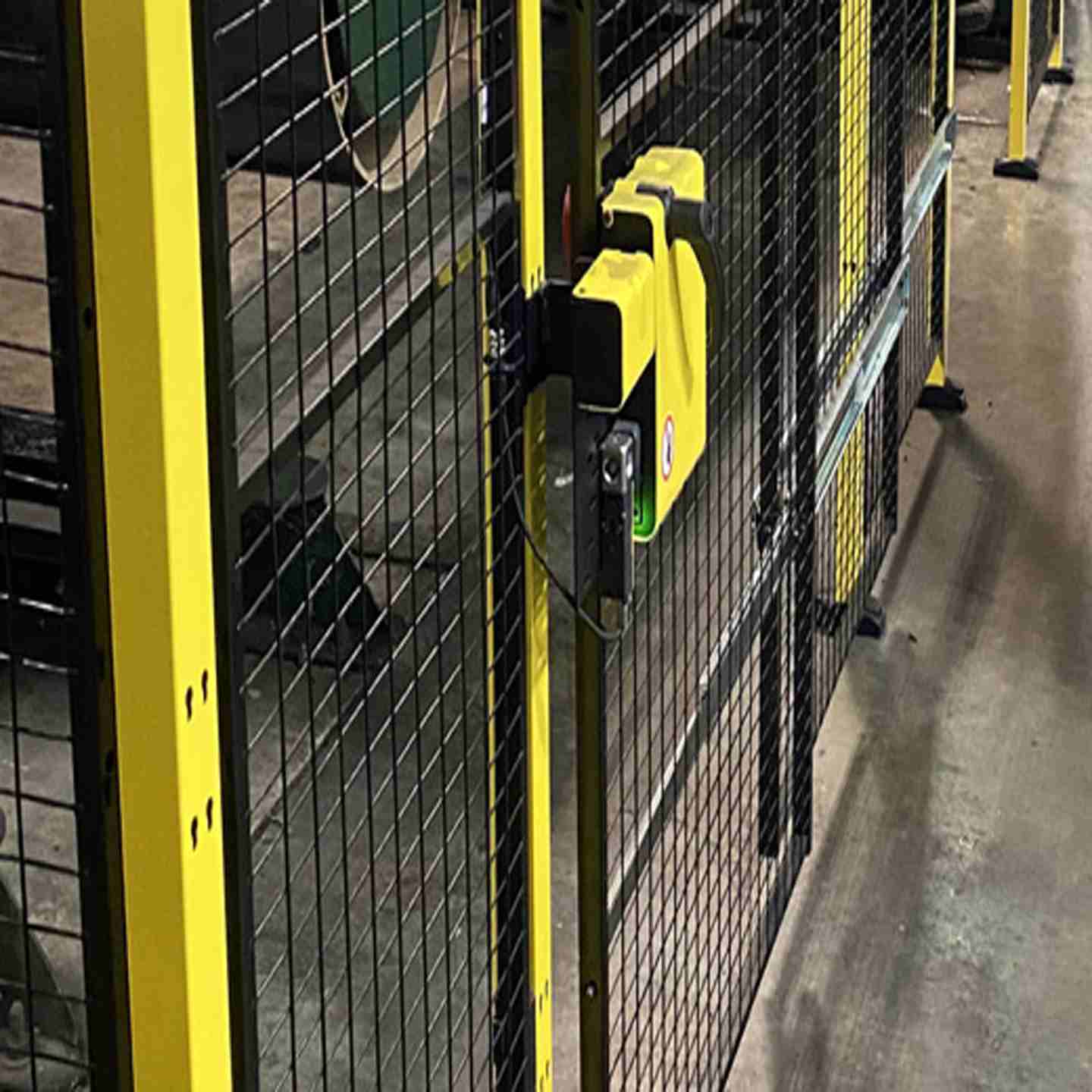
RFID Safety Interlock Switches secure machine access doors, gates, and covers until a verified safe condition is confirmed — preventing operator entry while hazardous motion is present. The Keyence GS Series is available in power-to-release (GS-50) and power-to-lock (GS-70) configurations, both rated to the highest safety standards (PLe / Category 4 / SIL 3 / Type 4) and built for industrial environments with IP65/67/69K protection.
Key Features
- Achieves PLe / Category 4 / SIL 3 / Type 4 safety ratings individually or cascaded
- Available in power-to-release (GS-50) and power-to-lock (GS-70) models to match your machine's hazard profile
- 2,000N locking force prevents forced entry into hazardous areas
- Cascade up to 25 units on a single OSSD pair, eliminating extra safety relays
- IP65 / IP67 / IP69K rated (TÜV SÜD certified) suited for washdown, coolant, and harsh industrial environments
- Built-in auxiliary output on every unit for per-door status monitoring via PLC or HMI
- On-board LED indicators (Open / Closed / Locked / Error) visible from multiple directions
- Articulated locking bolt with beveled entry point for misalignment and door sag tolerance
- Utilizes two OSSD safety outputs along with EDM and manual resets
- No need for a dedicated safety interlock relay or control box as they can be wired directly to a safety circuit
- Escape release option available for operators to open from inside the hazardous area

RFID Safety Interlock Switches (Locking) - Keyence GS Series
Power-to-release and power-to-lock guard locking switches rated to PLe / Category 4 / SIL 3 / Type 4
RFID Safety Interlock Switches secure machine access doors, gates, and covers until a verified safe condition is confirmed — preventing operator entry while hazardous motion is present. The Keyence GS Series is available in power-to-release (GS-50) and power-to-lock (GS-70) configurations, both rated to the highest safety standards (PLe / Category 4 / SIL 3 / Type 4) and built for industrial environments with IP65/67/69K protection.
Key Features
- Achieves PLe / Category 4 / SIL 3 / Type 4 safety ratings individually or cascaded
- Available in power-to-release (GS-50) and power-to-lock (GS-70) models to match your machine's hazard profile
- 2,000N locking force prevents forced entry into hazardous areas
- Cascade up to 25 units on a single OSSD pair, eliminating extra safety relays
- IP65 / IP67 / IP69K rated (TÜV SÜD certified) suited for washdown, coolant, and harsh industrial environments
- Built-in auxiliary output on every unit for per-door status monitoring via PLC or HMI
- On-board LED indicators (Open / Closed / Locked / Error) visible from multiple directions
- Articulated locking bolt with beveled entry point for misalignment and door sag tolerance
- Utilizes two OSSD safety outputs along with EDM and manual resets
- No need for a dedicated safety interlock relay or control box as they can be wired directly to a safety circuit
- Escape release option available for operators to open from inside the hazardous area
- Assembly:
- Safety relay or safety controller sold separately
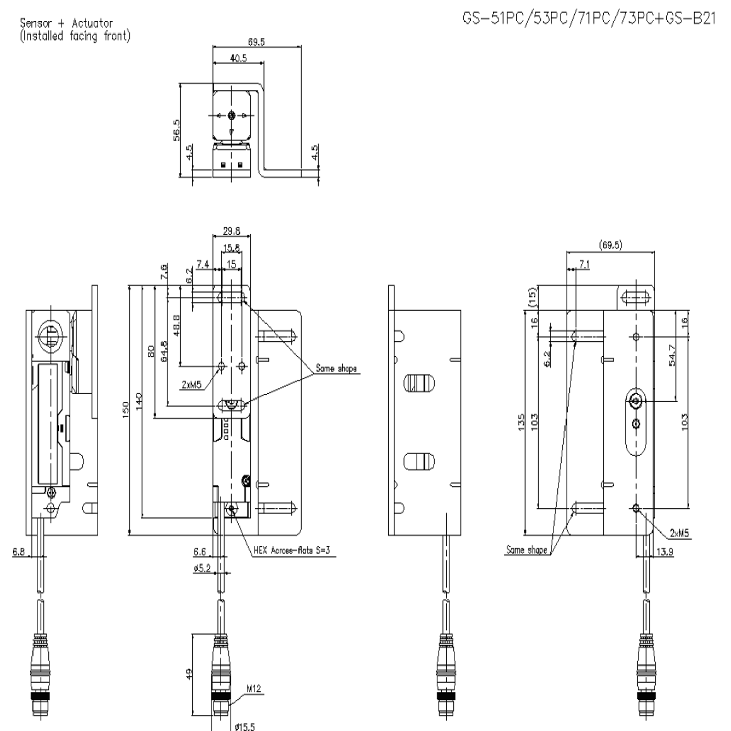
- Mounting brackets available separately (GS-B series)
- M12 × 8-pin connector (cable models include 5 m, 10 m, or 20 m PVC cable)
- Actuator key (coded or uncoded, model-dependent)
- Safety interlock switch body
- Output Options
- Standard type: PNP or NPN, 1 AUX output, cascade-ready
- Advanced (High Performance) type: 2 AUX outputs, manual reset, EDM, OSSD switching input
- Cascade Capacity
- Locking type (GS-50 / GS-70): Up to 25 units per OSSD pair
- Non-contact type (GS-10): Up to 30 units per OSSD pair
- Environmental Ratings
- IP65 / IP67 (IEC 60529), IP69K (ISO 20653) — TÜV SÜD certified
- NEMA Type 3 / 4X / 12 / 13
- Operating temperature: -20°C to +55°C (-4°F to 131°F)
- Vibration and shock resistant per IEC 60947-5-3
- Applicable Safety Standards
- EN 61508, IEC 61508(SIL2/SIL3)
- EN 62061, IEC62061(SIL CL2/SIL CL3)
- EN ISO13849-1: 2015(PLd, Category 2/PLe, Category 4) EN ISO14119(Type4)
- IEC 60947-5-3, EN 60947-5-3
- UL 61010-1, CAN/CSA-C22.2 No.61010-1
Mechanical / Alignment Issues
Won’t detect “closed”, won’t lock, intermittent operation
- Verify guard door alignment with actuator (check sagging, hinges, mounting)
- Inspect actuator and switch head for wear or damage
- Ensure correct actuator is being used (especially if coding/pairing is enabled)
- Check for vibration affecting engagement
- Confirm mounting hardware is tight and hasn’t shifted
Power & Configuration Issues
Lock won’t engage or release
- Verify correct voltage supply to the locking mechanism
- Confirm power-to-lock vs. power-to-release matches the model and application
- Ensure wiring polarity and terminals are correct
- Check for power drops or unstable supply
Status Indicators & Diagnostics
Unclear machine state or unexpected behavior
- Use onboard indicator lights (“open”, “closed”, “locked”, “error”) to identify state
- Compare indicator status with actual door condition
- Use diagnostic/AUX outputs for deeper monitoring
- Look for early warning signals (e.g., misalignment detection if available)
Wiring & Control System Issues
PLC/HMI not recognizing switch state
- Verify auxiliary output wiring continuity
- Check terminal connections for looseness or damage
- Confirm PLC/HMI is correctly reading the signal
- Validate safety relay or controller configuration
Cascaded System Issues
Multiple switches fail or system-wide fault
- Inspect each interlock in the cascade individually
- Look for one miswired or failed unit affecting the chain
- Confirm proper cascading configuration and addressing
Environmental Factors
Degraded or inconsistent performance over time
- Check for contamination (metal chips, coolant, dust)
- Clean actuator and switch mating surfaces
- Verify environmental rating is appropriate (IP65/67/69K vs actual conditions)
- Inspect for excessive vibration or shock
Safety & Release Function Issues
Lock doesn’t release when expected or emergency escape fails
- Test manual/escape release regularly
- Confirm lock releases under correct conditions
- Ensure compliance with safety requirements for egress
Functional Testing (After Install or Repair)
- Always perform a full cycle test:
- Open guard → machine must stop
- Close guard → verify proper detection
- Confirm lock behavior:
- Power-to-lock: lock engages with power
- Power-to-release: remains locked without power
- Ensure machine only restarts under safe conditions
Safety Compliance & Selection
System design concerns or audit failures
- Confirm required safety level (PLe / Category 4 / SIL3, etc.)
- Ensure correct switch type for hazard:
- Residual motion → use power-to-release
- Immediate stop → power-to-lock may be acceptable
- Verify actuator coding requirements (anti-tampering)
Preventive Maintenance
To avoid recurring issues:
- Inspect hinges, alignment, and actuator engagement regularly
- Check torque on mounting hardware
- Look for wear in mechanical components
- Verify lock/unlock operation hasn’t drifted
Fault Tracking & Continuous Improvement
- Log every fault or trip (date, condition, indicators)
- Look for patterns (e.g., repeated misalignment, vibration issues)
- Use data to identify root causes and prevent recurrence

