
Presence Sensing Safety Devices
3d Safety Radars by Inxpect
SIL2 / PLd / Category 3 millimeter-wave radar for access detection, safeguarding, & reset prevention
Inxpect 200 Series safety radars use 60 GHz millimeter-wave FMCW technology to detect human presence and access in three dimensions — delivering reliable protection in environments where dust, smoke, debris, rain, or variable lighting degrade optical sensors.
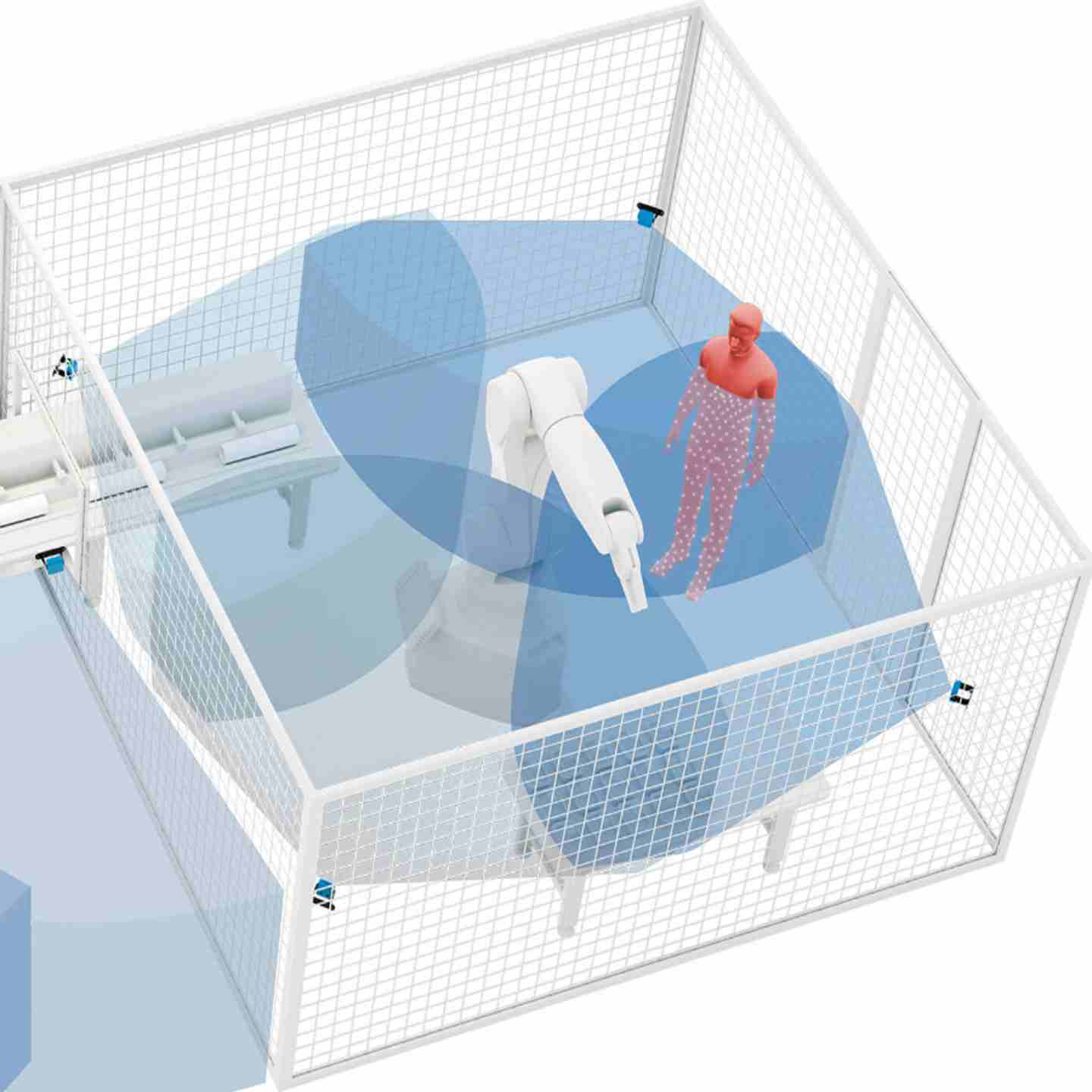
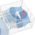
Unlike light curtains and laser scanners, these radars create true volumetric detection zones that can be shaped and dynamically reconfigured in real time, making them well-suited for robotic cells, AGVs, mobile gantries, and other applications where fixed planar protection is impractical. All sensors in the 200 Series are certified SIL2 (IEC 61508), PLd / Category 3 (ISO 13849), and Performance Class D (IEC/TS 62998-1), and are UL Listed.
Key Features
- SIL2 (IEC 61508) / PLd, Category 3 (ISO 13849) / Performance Class D (IEC/TS 62998-1) — UL Listed
- System response time under 100 ms, reducing required stopping distance and enabling tighter machine guarding
- Reliable detection in light, smoke, dust, debris, and rain up to 45 mm/h — no degradation in optical-challenging environments
- Sensor range up to 9 m (Pro Line 9M models: S201A-WL, S203A-WL, S203A-WLT), with max target speed up to 4 m/s
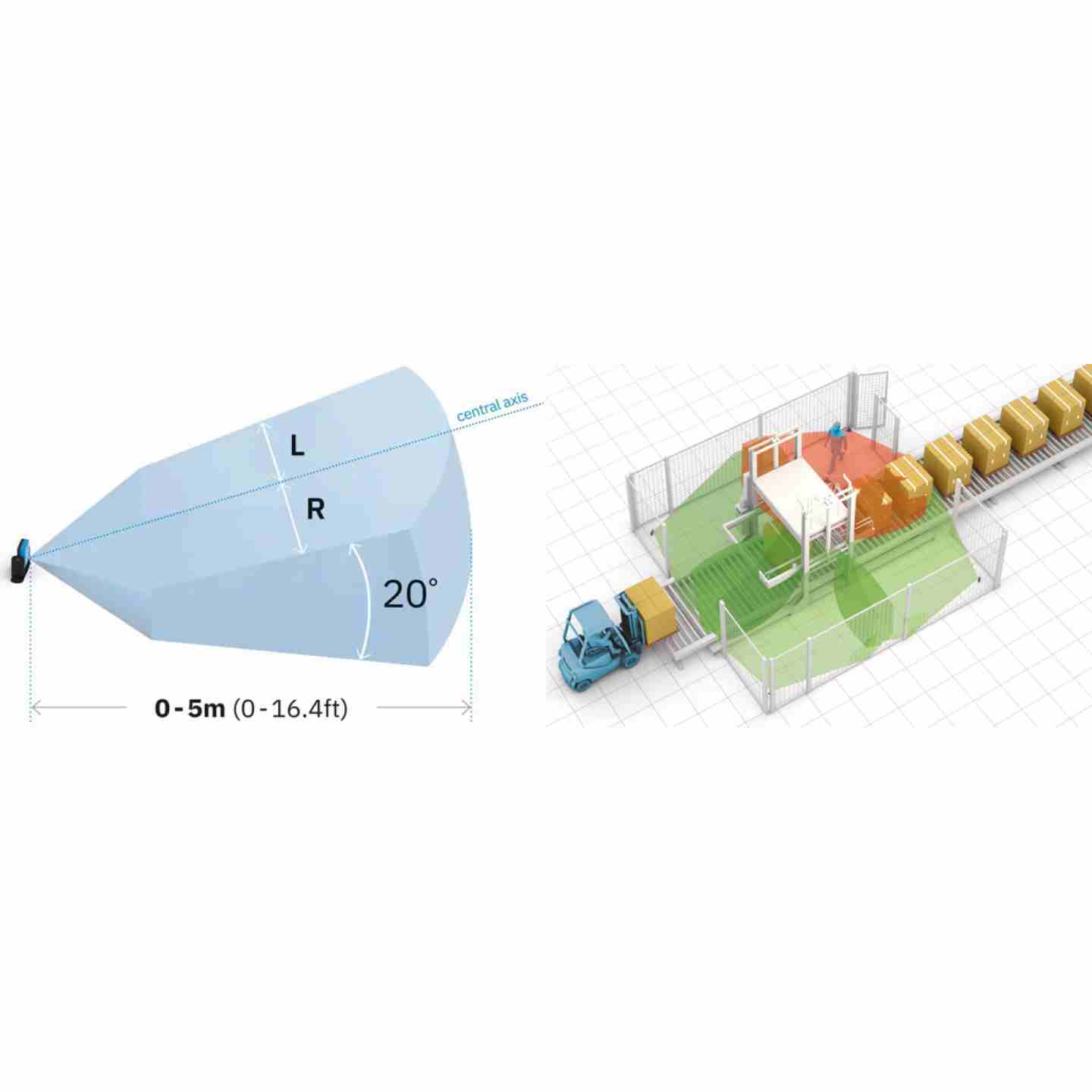
- Four independent, freely adjustable detection fields per sensor; aperture configurable in 5° increments from 10° to 100° (horizontal plane)
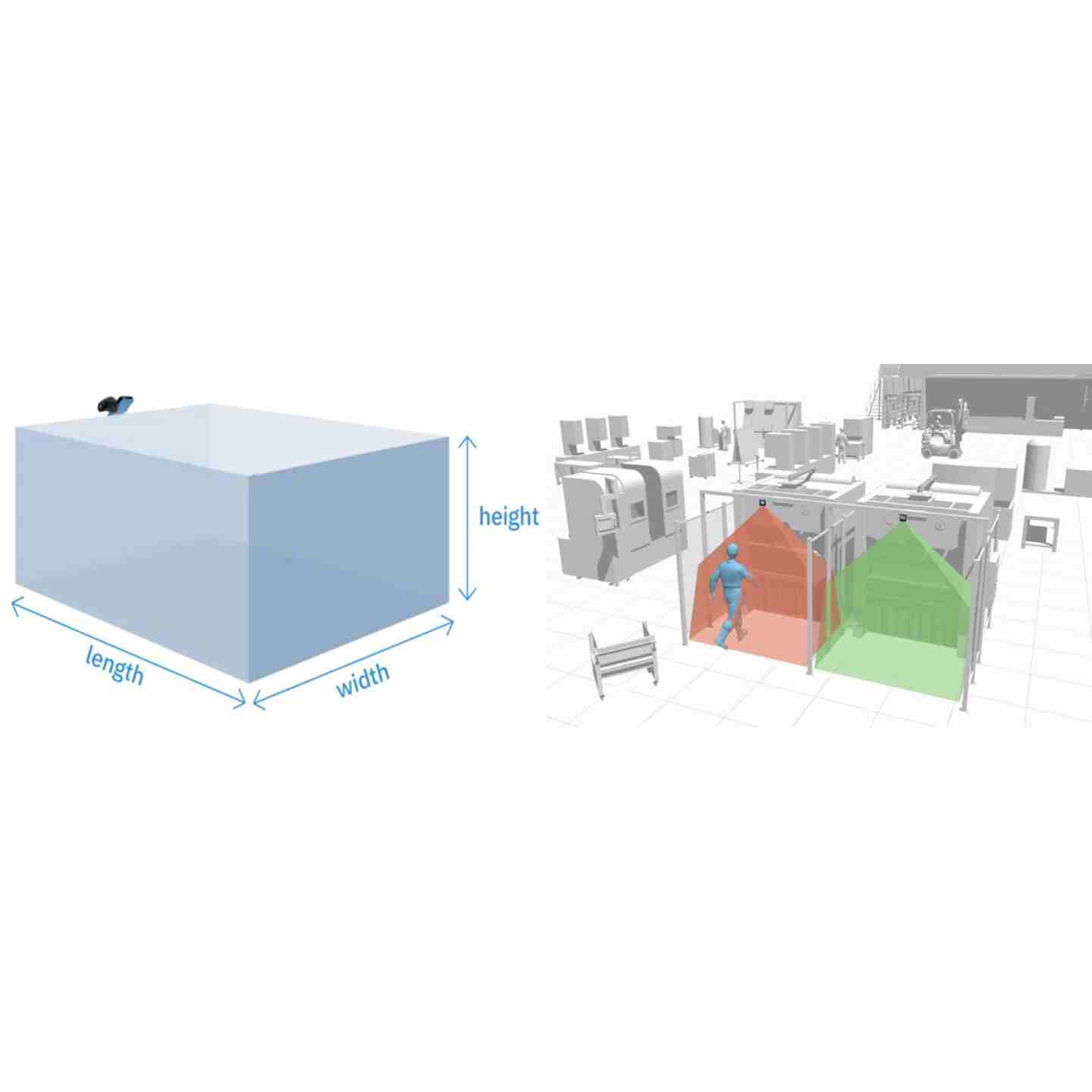
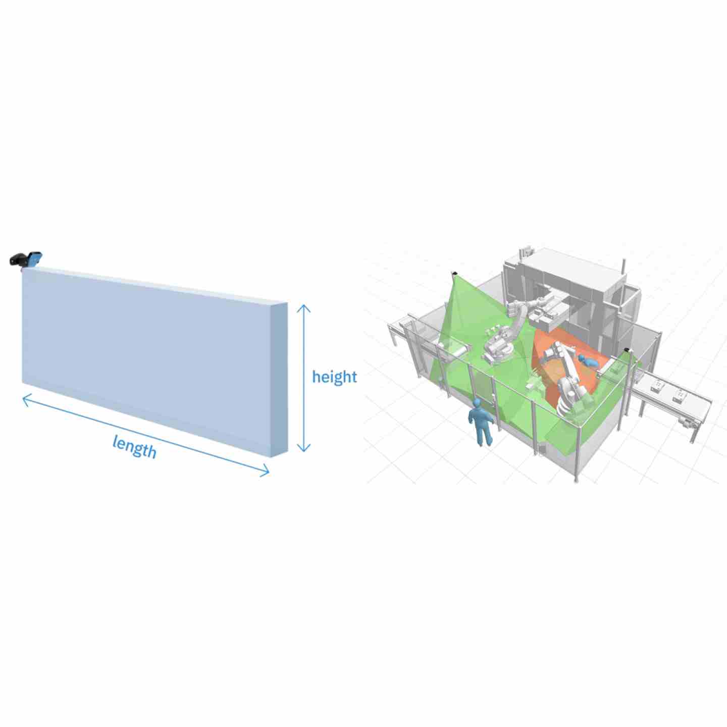
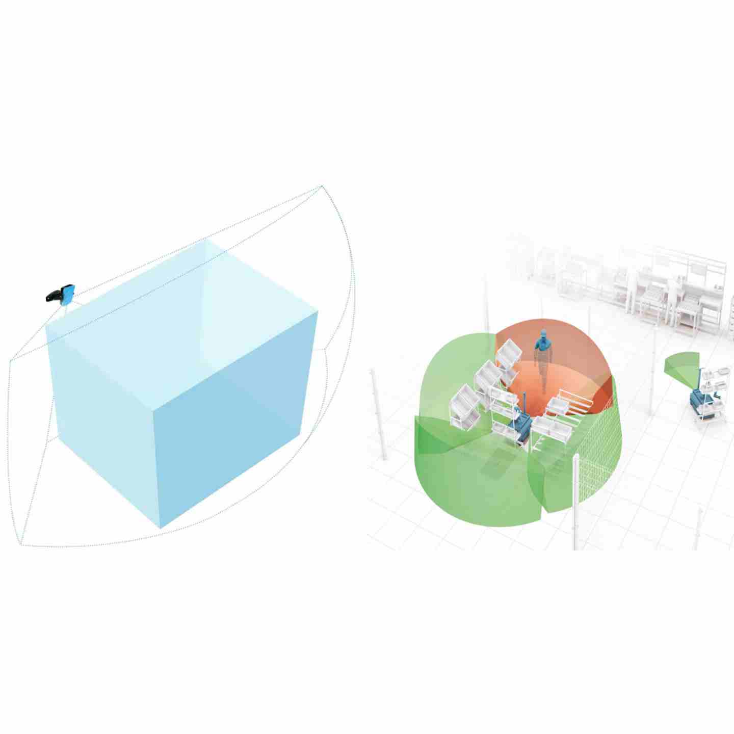
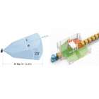
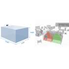
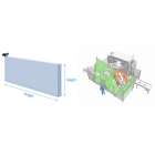
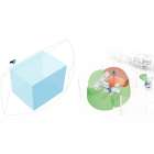
- Field of view shapes include Classic (symmetric or asymmetric), Corridor, and Cuboid — sensor selection determines available shapes
- Restart Prevention with optional Static Object Detection (S200 series): prevents machine restart when obstacles remain in the zone, critical for overhead gantries, AGVs, and autonomous vehicles
- Teach-In function (S203A-WT, S203A-WLT) automatically adapts detection range to changing environmental conditions without manual reconfiguration
- Programmable Muting: sensor groups can be temporarily muted to allow safe access to defined zones without disabling the full safety system
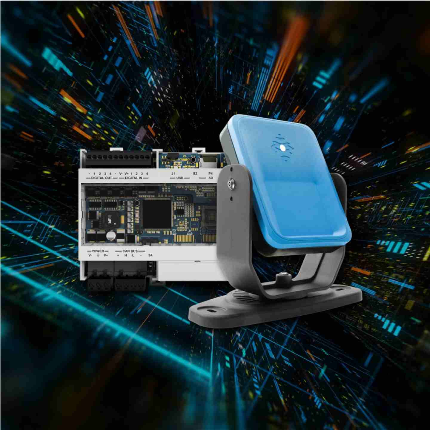
- Scalable system architecture: one Inxpect control unit supports up to 6 radar sensors, with up to 32 dynamically selectable zone configurations
- IP67 rated, operating range –30°C to +60°C — suitable for indoor and outdoor industrial environments
- Configured via Inxpect Safety Studio with 3D field-of-view visualization, offline project mode, guided validation, and auto-generated configuration reports








3d Safety Radars by Inxpect
SIL2 / PLd / Category 3 millimeter-wave radar for access detection, safeguarding, & reset prevention
Inxpect 200 Series safety radars use 60 GHz millimeter-wave FMCW technology to detect human presence and access in three dimensions — delivering reliable protection in environments where dust, smoke, debris, rain, or variable lighting degrade optical sensors.
Unlike light curtains and laser scanners, these radars create true volumetric detection zones that can be shaped and dynamically reconfigured in real time, making them well-suited for robotic cells, AGVs, mobile gantries, and other applications where fixed planar protection is impractical. All sensors in the 200 Series are certified SIL2 (IEC 61508), PLd / Category 3 (ISO 13849), and Performance Class D (IEC/TS 62998-1), and are UL Listed.
Key Features
- SIL2 (IEC 61508) / PLd, Category 3 (ISO 13849) / Performance Class D (IEC/TS 62998-1) — UL Listed
- System response time under 100 ms, reducing required stopping distance and enabling tighter machine guarding
- Reliable detection in light, smoke, dust, debris, and rain up to 45 mm/h — no degradation in optical-challenging environments
- Sensor range up to 9 m (Pro Line 9M models: S201A-WL, S203A-WL, S203A-WLT), with max target speed up to 4 m/s
- Four independent, freely adjustable detection fields per sensor; aperture configurable in 5° increments from 10° to 100° (horizontal plane)
- Field of view shapes include Classic (symmetric or asymmetric), Corridor, and Cuboid — sensor selection determines available shapes
- Restart Prevention with optional Static Object Detection (S200 series): prevents machine restart when obstacles remain in the zone, critical for overhead gantries, AGVs, and autonomous vehicles
- Teach-In function (S203A-WT, S203A-WLT) automatically adapts detection range to changing environmental conditions without manual reconfiguration
- Programmable Muting: sensor groups can be temporarily muted to allow safe access to defined zones without disabling the full safety system
- Scalable system architecture: one Inxpect control unit supports up to 6 radar sensors, with up to 32 dynamically selectable zone configurations
- IP67 rated, operating range –30°C to +60°C — suitable for indoor and outdoor industrial environments
- Configured via Inxpect Safety Studio with 3D field-of-view visualization, offline project mode, guided validation, and auto-generated configuration reports
- Assembly:
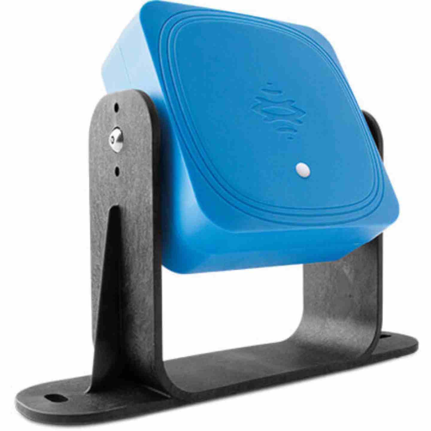
- Inxpect 200 Series radar sensor(s) — model determined by required function (access detection, safeguarding, or presence sensing), range (5 m or 9 m), and field of view type
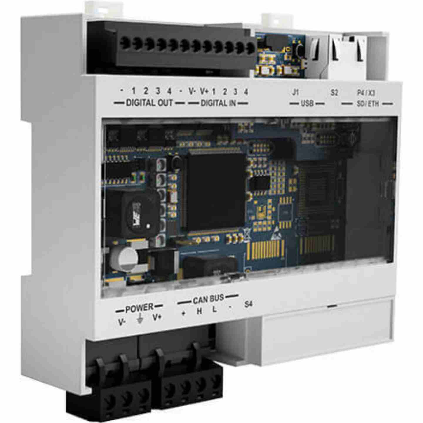
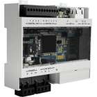
- Inxpect control unit — supports up to 6 sensors; communicates to machine PLC via digital I/O or optional fieldbus (ProfiSafe/EtherNet-based safety protocols)
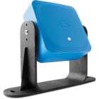
- 3-axis mounting bracket (included with sensor) — allows rotation on X, Y, and Z axes for precise positioning
- Two 5-pin M12 connectors per sensor (1 male, 1 female) for daisy-chain bus connection; CAN bus termination connector (120 Ω) sold separately and required at the end of the sensor chain
- Inxpect Safety Studio software (downloadable); installation, validation, and configuration reporting included in the workflow
- User documentation and regulatory compliance materials (accessible via QR code on each sensor)
- Output Options
- OSSD safety outputs to safety relay or safety-rated PLC input (two-channel)
- Digital I/O interface to machine PLC (standard across all control unit variants)
- Optional fieldbus/EtherNet safety communication for real-time exchange of target position data (distance and angle) with machine control system
- Programmable Muting input available at the control unit for zone group management
- Environmental Ratings
- Degree of protection: IP67 (IEC 60529)
- Operating temperature: –30°C to +60°C (–22°F to +140°F)
- Resistant to light, smoke, dust, debris, and rain up to 45 mm/h
- Sensor housing: PA66 front + aluminum back; bracket: PA66 with glass fiber reinforcement
- Radar frequency: 60 GHz millimeter-wave V-band (FMCW)
Nuisance Trips / Unexpected Zone Activation
Machine stops without personnel in the zone; frequent false alarms
- Confirm no large metallic reflectors (conveyors, machinery, structural steel) are positioned within or adjacent to the configured detection zone — strong radar returns from fixed objects can register as motion if the zone boundary intersects them
- Verify that zone boundaries are set with adequate clearance from known static infrastructure; use Inxpect Safety Studio's 3D visualization to review where the field edges fall relative to the physical environment
- Check whether background filtering is working as expected — the radars filter static objects by default, but moving machinery outside the intended zone can register as access events if fields are not tightly shaped
- If the environment has recently changed (new equipment, racking, partitions), use the Teach-In function (S203A-WT / S203A-WLT / S203A-WL models) to re-learn the environment and update detection distances accordingly
- For Omni Line cuboid configurations, confirm that cuboid dimensions (minimum 50 × 50 × 100 cm) and positions are correctly mapped to the actual hazard geometry
Failure to Detect / Zone Not Triggering
Personnel enter the detection zone without triggering a stop
- Verify sensor mounting angle and orientation using the 3-axis bracket — confirm the detection plane covers the full access path, including low-approach angles (crouching, kneeling) and lateral approaches
- Check that all 4 detection fields are configured and that field aperture angles (adjustable in 5° increments) cover the full horizontal extent of the hazard zone
- For S202A-MV (Presence Sensing) and S202A-MS (Safeguarding) Plug&Safe models, confirm installation height is within spec: MV requires 250–300 cm from reference plane; MS requires 100–250 cm
- Confirm the configured minimum detection distance (0.2 m minimum set distance across all Pro Line sensors) is appropriate — targets very close to the sensor face may fall within the excluded near zone
- Review maximum target speed setting relative to the application: Pro Line and Plug&Safe models are rated to 1.6–2 m/s; if personnel can approach faster (e.g., Pro Line 9M applications at up to 4 m/s), ensure the correct sensor family is selected
- Check sensor-to-control-unit CAN bus wiring and confirm the termination resistor (120 Ω) is installed at the correct end of the sensor chain — an improperly terminated bus can cause communication dropouts that appear as zone failures
Restart Prevention Not Functioning Correctly
Machine restarts while personnel or obstacles remain in the zone; or fails to restart after zone is cleared
- Confirm the Restart Prevention safety function is configured and active in the Inxpect Safety Application — it must be explicitly enabled; it is separate from access detection
- Verify Restart Timeout (4 s default across 200 Series) is appropriate for the application and consistent with how the PLC is reading the zone-clear signal
- If the machine must also be prevented from restarting when non-personnel obstacles remain in the zone (tools, parts, fixtures), enable Static Object Detection — available on S200 series sensors; note this is disabled by default and must be activated
- Test restart prevention by placing a static object in the zone with personnel removed — with Static Object Detection enabled, the machine should remain in stop state; with it disabled, the machine should be permitted to restart after the timeout
Teach-In Function Behaving Unexpectedly
Sensor not adapting to environment changes; false teach-in range applied
- Confirm the Teach-In input is being triggered correctly — it must be activated via a dedicated external input; the sensor will not enter learning mode automatically
- Ensure the learning area is free of personnel before triggering Teach-In — the function sets the last detection field's range based on the nearest static target detected in the learning volume; a person in the zone will produce an incorrect (too-short) learned range
- After Teach-In completes, verify updated detection distances in Inxpect Safety Studio before returning the machine to production
- If Teach-In is not available on the installed sensor model, confirm that the application actually requires it — S201A-W, S201A-WL, S202A-MV, S202A-MS, S202A-MC2, and S202A-MC4 do not have this function; it is exclusive to S203A-WT and S203A-WLT
System Communication / Control Unit Faults
Sensor not recognized by control unit; fieldbus errors; no safety output
- Check all 5-pin M12 connectors at each sensor for seating, damage, and correct pin assignment (1 male, 1 female per sensor for bus pass-through)
- Confirm the CAN bus termination connector (120 Ω) is installed at the final sensor in the chain — not at an intermediate sensor
- In Inxpect Safety Studio, review the sensor list and diagnostic status; a sensor shown as offline or in fault typically indicates a wiring or address conflict
- If using optional fieldbus output to PLC, verify the network configuration matches the control unit variant (not all control unit variants support all fieldbus protocols — confirm at time of specification)
- Confirm power supply to the control unit is 12 V DC ±20%; individual sensors draw 2.2–2.6 W depending on model — verify the control unit power supply is adequately sized for the number of sensors in the system
Performance Degraded in Harsh Environments
Increased false alarms or missed detections in dusty, wet, or high-vibration environments
- While radar is substantially immune to dust, smoke, and moisture, heavy accumulation of conductive metallic debris (weld spatter, metal shavings) directly on the sensor face can attenuate the radar signal — clean the sensor face and bracket periodically in these environments
- In high-vibration installations (presses, compactors, heavy stamping), confirm the mounting bracket hardware is torqued and hasn't shifted — even small angular displacement can move the detection zone relative to the hazard boundary
- Verify operating temperature is within range (–30°C to +60°C) — ambient conditions outside this range require additional thermal management
Muting / Zone Reconfiguration Not Working as Expected
Muted zones not clearing; zone configurations not switching on command
- Confirm muting is configured as a sensor group (not individual sensors) in the Inxpect Safety Application — the muting function operates on defined groups, not on the full system simultaneously
- Verify the muting input signal to the control unit is being received correctly; check wiring continuity and PLC output logic
- Up to 32 different zone configurations can be selected dynamically via the control unit — confirm the correct configuration index is being commanded and that the selection input is properly wired and decoded
Preventive Maintenance
- Inspect sensor face and bracket for physical damage, debris accumulation, and mounting hardware torque at each scheduled maintenance interval
- Re-verify detection zone coverage annually or any time the machine cell layout, guarding, or adjacent equipment changes — use Inxpect Safety Studio to compare current configuration against the original validated setup
- Confirm all M12 connectors are fully seated and show no signs of corrosion or mechanical wear, particularly in washdown or wet environments
- Re-run the guided validation procedure in Inxpect Safety Studio after any sensor replacement, firmware update, or configuration change — generate and retain a new configuration report for compliance records
Fault Tracking
- Log all safety trips with date, time, sensor/zone identifier, and observed conditions in the area at the time of the event
- Review the Inxpect Safety Studio diagnostic history after any unplanned trip to identify whether the event was triggered by an actual detection or a system/communication fault
- Track patterns over time: repeated trips from the same sensor or zone typically indicate a mounting, configuration, or environmental issue rather than a sensor hardware failure — address root cause rather than resetting and continuing