
Machine Tool Guards and Shields
Surface Grinder Guards
Contain abrasive wheel fragments, suppress sparks and protect from entanglement and flying debris
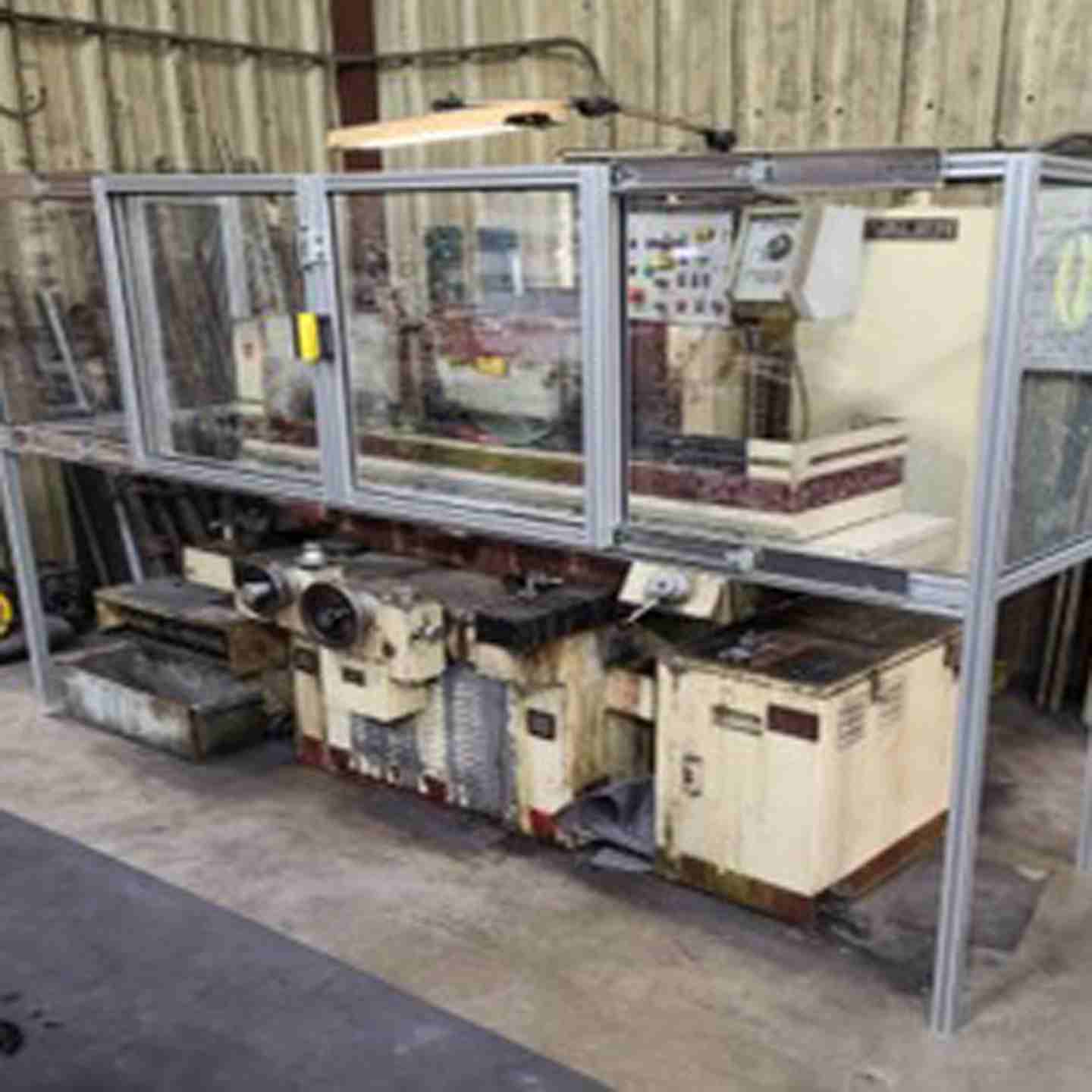
The Surface Grinder Guard protects operators from the rotating grinding wheel, potential wheel breakage, and part ejection during manual or CNC automatic surface grinding operations. Every guard is engineered to fit your specific make and model rather than sold as a generic kit. The frame is built from 40mm square aluminum T-slot extrusion with sliding polycarbonate doors that ride on UHMW bearing pads, secured by a spring loaded stainless steel deadbolt latch. These guards are built for both current and legacy surface grinders, including Boyar-Schultz, Harig, Okamoto, Chevalier, Reid, Brown & Sharpe, K.O. Lee, Kent, Mitsui, Jones & Shipman, Acer, Clausing, and custom or unlisted machines, with an optional electrical safety interlock available.
Key Features
- Custom built and engineered in CAD to fit your specific surface grinder: submit a completed measurement form, machine make and model, and desired features for a pre-construction drawing before fabrication
- Compatible with current and legacy surface grinders, including Boyar-Schultz, Harig, Okamoto, Chevalier, Reid, Brown & Sharpe, K.O. Lee, Kent, Mitsui, Jones & Shipman, Acer, and Clausing, plus custom or unlisted machines
- Frame constructed from 40mm square industrial aluminum T-slot extrusion, in clear anodized (standard) or orange powder coated (optional) finish
- 1/4 inch thick impact resistant polycarbonate (Lexan) doors, seated in rubber molding within the extrusion's T-slot
- Sliding doors ride on white UHMW bearing pads in the outer T-slot; door opening length is designed into the build for your access needs
- Safety latch uses a positive spring loaded deadbolt made from stainless steel and aluminum
- End panels adjust along the width of the main frame and mount via included angle brackets, either to the machine's existing sheet metal shroud, the ends of the table, or by drilling and bolting anywhere along the front T-slot
- Optional electrical safety interlock prevents the machine from running until the guard doors are shut, once integrated into the grinder's control
- Choice of interlock hardware: tongue style (locking or non-locking), magnetic non-contact switch, or RFID non-contact switch
- Floor mounted configuration available, anchored to the concrete floor, for machines that can't be guard mounted directly
Surface Grinder Guards
Contain abrasive wheel fragments, suppress sparks and protect from entanglement and flying debris
The Surface Grinder Guard protects operators from the rotating grinding wheel, potential wheel breakage, and part ejection during manual or CNC automatic surface grinding operations. Every guard is engineered to fit your specific make and model rather than sold as a generic kit. The frame is built from 40mm square aluminum T-slot extrusion with sliding polycarbonate doors that ride on UHMW bearing pads, secured by a spring loaded stainless steel deadbolt latch. These guards are built for both current and legacy surface grinders, including Boyar-Schultz, Harig, Okamoto, Chevalier, Reid, Brown & Sharpe, K.O. Lee, Kent, Mitsui, Jones & Shipman, Acer, Clausing, and custom or unlisted machines, with an optional electrical safety interlock available.
Key Features
- Custom built and engineered in CAD to fit your specific surface grinder: submit a completed measurement form, machine make and model, and desired features for a pre-construction drawing before fabrication
- Compatible with current and legacy surface grinders, including Boyar-Schultz, Harig, Okamoto, Chevalier, Reid, Brown & Sharpe, K.O. Lee, Kent, Mitsui, Jones & Shipman, Acer, and Clausing, plus custom or unlisted machines
- Frame constructed from 40mm square industrial aluminum T-slot extrusion, in clear anodized (standard) or orange powder coated (optional) finish
- 1/4 inch thick impact resistant polycarbonate (Lexan) doors, seated in rubber molding within the extrusion's T-slot
- Sliding doors ride on white UHMW bearing pads in the outer T-slot; door opening length is designed into the build for your access needs
- Safety latch uses a positive spring loaded deadbolt made from stainless steel and aluminum
- End panels adjust along the width of the main frame and mount via included angle brackets, either to the machine's existing sheet metal shroud, the ends of the table, or by drilling and bolting anywhere along the front T-slot
- Optional electrical safety interlock prevents the machine from running until the guard doors are shut, once integrated into the grinder's control
- Choice of interlock hardware: tongue style (locking or non-locking), magnetic non-contact switch, or RFID non-contact switch
- Floor mounted configuration available, anchored to the concrete floor, for machines that can't be guard mounted directly
Assembly / What's Included
- 40mm aluminum T-slot extrusion frame
- Sliding 1/4 inch polycarbonate (Lexan) doors with UHMW bearing pads
- Spring loaded stainless steel deadbolt latch
- Adjustable end panels
- Mounting angle brackets
Each Surface Grinder Guard is custom built to your machine make and model, and desired features.
Configuration Options
- Standard finish: clear anodized aluminum
- Optional finish: orange powder coated
- Optional electrical safety interlock: tongue style (locking or non-locking), magnetic non-contact switch, or RFID non-contact switch
- Optional floor mounted configuration, anchored to the concrete floor, for machines where direct mounting isn't possible
- Door opening length designed to your specified access needs
Materials & Construction
- 40mm square industrial aluminum T-slot extrusion, clear anodized (standard) or orange powder coated (optional)
- 1/4 inch thick impact resistant polycarbonate (Lexan) doors, seated in rubber molding within the T-slot
- White UHMW bearing pads for door sliding action
- Stainless steel and aluminum spring loaded deadbolt latch
- Adjustable angle brackets for end panel and frame mounting
Sliding Door Doesn't Move Smoothly
Door binds, sticks, or is hard to slide open or closed
- Inspect the white UHMW bearing pads in the outer T-slot for wear, debris, or misalignment
- Clean the T-slot track of grinding swarf, coolant residue, or abrasive dust, which can accumulate and impede sliding action
- Confirm the door hasn't shifted out of its designed opening travel
- Check that the frame hasn't been bent or racked out of square, which can bind the door path
Latch Doesn't Engage or Hold Securely
Spring loaded deadbolt won't lock, or door isn't held closed
- Inspect the deadbolt mechanism for debris or damage
- Confirm the strike position still aligns with the deadbolt after any door or frame adjustment
- Check the spring action of the latch; a weak or damaged spring may need replacement
- Verify the door is fully seated in its track before attempting to latch
Guard Doesn't Fit the Machine Correctly
Gaps, misalignment, or interference with the table or shroud
- Confirm the guard was built from accurate measurements submitted on the measurement form; a remeasure may be needed if the machine has since been modified
- Adjust the end panels along the width of the main frame using the angle brackets before final mounting
- End Panel or Mounting Bracket Issues
Panels won't stay in position; guard is unstable
- Confirm angle brackets are securely mounted to the existing sheet metal shroud, table ends, or drilled and bolted along the front T-slot as intended
- Recheck that end panels are adjusted and locked along the width of the main frame
- For floor mounted configurations, verify the concrete anchors are properly torqued and haven't loosened over time
Safety Interlock Does Not Signal Correctly (If Selected)
Machine doesn't stop when doors open; control doesn't respond to switch state
- Confirm which interlock hardware was selected (tongue style locking or non-locking, magnetic non-contact, or RFID non-contact) and reference its specific wiring requirements
- Verify the interlock is wired to a compatible motor control device or safety relay; the switch alone typically can't directly interrupt the grinder's spindle motor
- Check wiring connections at the switch, motor control, and any terminal strips for looseness or damage
- For magnetic or RFID non-contact switches, confirm correct alignment and supply voltage per the switch type
- Test the interlock in isolation by manually cycling the door and verifying the output state changes at the motor control or relay input
Shield & Material Issues
Visible wear, cracking, or reduced visibility through the polycarbonate
- Inspect the polycarbonate (Lexan) doors for cracks, chips, or stress marks after any impact event; replace immediately if damage is found
- Clean the polycarbonate with a mild soap and water solution; avoid solvent based cleaners (acetone, MEK, lacquer thinner), which will craze and weaken the Lexan
- Confirm the rubber molding around the polycarbonate in the T-slot remains intact and properly seated
Preventive Maintenance
To keep the guard performing reliably:
- Clean the sliding door tracks and UHMW bearing pads regularly, especially in high swarf or coolant environments
- Inspect the deadbolt latch and spring action periodically
- Clean the polycarbonate doors on a regular schedule using approved cleaners only
- For interlocked units, cycle the doors at each maintenance interval and verify the motor control responds correctly to the switch state
- Recheck mounting bracket and floor anchor hardware for looseness over time
Fault Tracking & Continuous Improvement
- Log any hardware adjustment, shield replacement, or interlock fault, including the machine and date
- Look for recurring patterns, such as repeated track binding tied to a specific machine's swarf or coolant levels
- Use this history to plan hardware maintenance and shield replacement before damage affects protection