Integrated Machine Safety Controls
Zero-Speed Safety Monitoring Systems
Monitors motor rotation and verifies zero-speed conditions for safe operator entry and maintenance.
Zero speed monitoring devices detect when a machine's shaft, rotor, or conveyor has completely stopped before allowing access to hazardous areas, preventing operators from opening guards or entering a danger zone until motion has safely reached zero. PowerSafe builds these safety circuits around a configurable safety controller which aggregates a rotation sensor's safety output along with guard interlocks, emergency stops, and other safety devices into one Category 4/PLe, SIL 3 rated system.
Key Features
- Achieves Category 4, PLe performance (ISO/EN13849-1:2015) and SIL 3 (IEC 61508, IEC 62061), UL1998 recognized
- 14 configurable safety inputs and 4 safety outputs, enough to combine a rotation or speed sensor with guard interlocks, emergency stops, and light curtains in one system
- 1 safety relay output rated 250 VAC 6A / 30 VDC 6A resistive, suited to switching a guard door lock or contactor directly
- GC-Link ports reduce wiring when paired with other Keyence safety devices such as light curtains, interlock switches, and laser scanners
- Built in 1.77 inch color LCD display shows live device status, event history, and timing charts for troubleshooting
- Configured through drag and drop software over USB rather than hardwired logic, so trip thresholds and timing can be adjusted without rewiring
- Safety input type accepts contact output or PNP output devices, compatible with most proximity sensors and encoders used for shaft speed detection
- 24 VDC powered (Class 2), maximum 200 mA power consumption
- Compact 85 x 95 x 90 mm footprint for panel mounting
- 4 AUX outputs (PNP or NPN selectable) for status monitoring, plus test outputs for input device diagnostics
Zero-Speed Safety Monitoring Systems
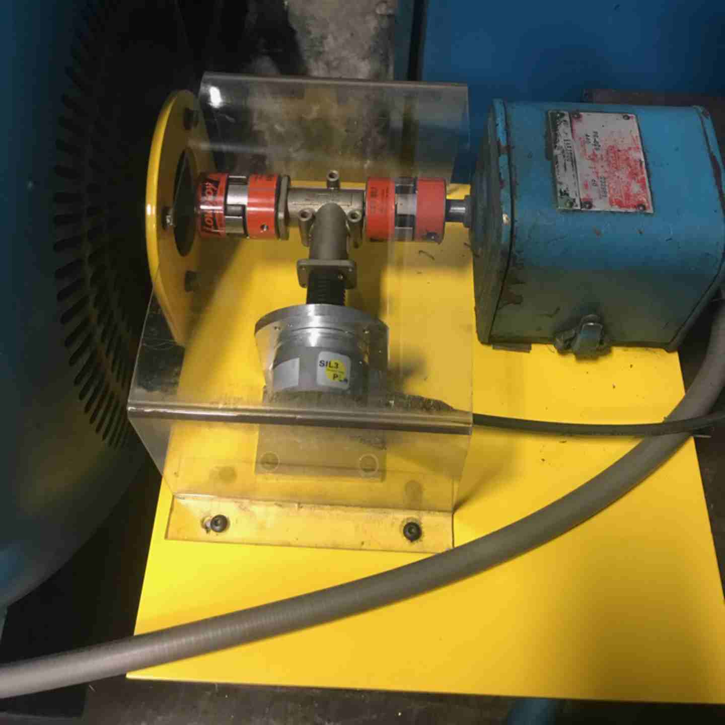
Monitors motor rotation and verifies zero-speed conditions for safe operator entry and maintenance.
Zero speed monitoring devices detect when a machine's shaft, rotor, or conveyor has completely stopped before allowing access to hazardous areas, preventing operators from opening guards or entering a danger zone until motion has safely reached zero. PowerSafe builds these safety circuits around a configurable safety controller which aggregates a rotation sensor's safety output along with guard interlocks, emergency stops, and other safety devices into one Category 4/PLe, SIL 3 rated system.
Key Features
- Achieves Category 4, PLe performance (ISO/EN13849-1:2015) and SIL 3 (IEC 61508, IEC 62061), UL1998 recognized
- 14 configurable safety inputs and 4 safety outputs, enough to combine a rotation or speed sensor with guard interlocks, emergency stops, and light curtains in one system
- 1 safety relay output rated 250 VAC 6A / 30 VDC 6A resistive, suited to switching a guard door lock or contactor directly
- GC-Link ports reduce wiring when paired with other Keyence safety devices such as light curtains, interlock switches, and laser scanners
- Built in 1.77 inch color LCD display shows live device status, event history, and timing charts for troubleshooting
- Configured through drag and drop software over USB rather than hardwired logic, so trip thresholds and timing can be adjusted without rewiring
- Safety input type accepts contact output or PNP output devices, compatible with most proximity sensors and encoders used for shaft speed detection
- 24 VDC powered (Class 2), maximum 200 mA power consumption
- Compact 85 x 95 x 90 mm footprint for panel mounting
- 4 AUX outputs (PNP or NPN selectable) for status monitoring, plus test outputs for input device diagnostics
Assembly / What's Included
- Controller unit
- Configuration software
- Wiring guide for your safety circuit
Input/Output & Electrical Specifications
- Safety inputs: 14, accepting contact output or PNP output devices (Type 3); ON level min. 11V/2mA, OFF level max. 5V/1.5mA
- Safety outputs: 4 PNP transistor outputs (DC-13, Type 0.5), max. 500 mA load current
- Safety relay output: 1 (3a), rated 250 VAC 6A / 30 VDC 6A resistive, 240 VAC 2A / 24 VDC 1A inductive; mechanical life of at least 100,000 operations at rated load
- AUX outputs: 4, PNP or NPN selectable, max. 100 mA (PNP) / 20 mA (NPN)
- Test outputs available; GC-Link: 2 ports for reduced wiring with other Keyence safety devices
- Communication: USB 2.0 for configuration; no Ethernet
- Power supply: 24 VDC (-20 to +20%), max. 200 mA consumption
Environmental Ratings
- Ambient temperature: -10°C to +55°C (14°F to 131°F), no freezing
- Storage temperature: -25°C to +70°C (-13°F to 158°F), no freezing
- Relative humidity: 5 to 85%, no condensation
- Vibration resistance: 5 to 9 Hz at 3.5 mm half amplitude; 9 to 150 Hz at 10 m/s², 10 times each in X, Y, Z
- Shock resistance: 150 m/s², 11 ms, 3 times each in X, Y, Z
- Pollution degree 2; overvoltage category II (III for the relay output section)
Applicable Safety Standards
- ISO/EN13849-1:2015
- SIL 3 IEC 61508
- IEC 62061
- UL1998
Safety Input Faults
Controller shows a fault on the speed/rotation sensor input
- Confirm the sensor output type (contact or PNP) matches the configured input type on the GC-1000R
- Verify wiring meets the ON level (min. 11V/2mA) and OFF level (max. 5V/1.5mA) specifications
- Check that cable length is within the 100 m maximum for safety inputs
- Review the built in protection circuit's fault indication on the LCD for wrong wiring
Relay Output Issues
Guard lock or interlock doesn't release at zero speed
- Confirm the safety relay output is wired within its rated load (250 VAC 6A / 30 VDC 6A resistive, or 240 VAC 2A / 24 VDC 1A inductive)
- Verify a 10A fast blow fuse is installed in series with each contact per IEC 61131-2 requirements
- Check relay contact wear if approaching the rated mechanical life (100,000 to 500,000 operations depending on load)
- Confirm the safety program's logic correctly ties the sensor input to the relay output
Configuration & Software Issues
Settings don't match the installed sensor or trip thresholds
- Reconnect via USB and verify the configuration in the dedicated software matches the installed sensor and safety logic
- Confirm automatic terminal assignment completed correctly during setup
- Use the simulation mode to verify logic before deploying to the live system
- Recheck trip thresholds and timing against your machine's actual coasting behavior
GC-Link & Wiring Issues
Connected Keyence device not recognized
- Confirm GC-Link enabled devices are connected to the correct port
- Verify cable connections are fully seated
- Check the built in display for interlock status and error codes specific to the connected device
- Confirm non-GC-Link devices are wired to standard safety inputs, not GC-Link ports
Display & Monitoring Issues
LCD doesn't show expected status or history
- Use the event history function to review recent faults and generate a timing chart
- Confirm the display buttons (3 operation keys plus 1 BACK key) are responding correctly
- Power cycle the controller if the display becomes unresponsive
Environmental Factors
Degraded or inconsistent performance over time
- Confirm ambient temperature stays within -10°C to +55°C (14°F to 131°F)
- Check for condensation if humidity approaches the 85% maximum
- Inspect for excessive vibration or shock beyond the rated levels, especially on high inertia equipment
Safety Compliance & Selection
System design concerns or audit findings
- Confirm the Category 4/PLe, SIL 3 rating is maintained through the full safety string, including the rotation sensor and any downstream devices
- Verify the specific sensor used for zero speed detection is documented and rated for this application; this isn't specified in the GC-1000R materials reviewed
- Ensure periodic function testing and coasting time verification are documented per your safety program
Preventive Maintenance
To avoid recurring issues:
- Verify sensor alignment and wiring on a regular schedule
- Confirm safety relay output contacts show no signs of wear
- Recheck configuration and trip thresholds after any machine control changes
- Review event history periodically for early warning patterns
Fault Tracking & Continuous Improvement
- Use the GC-1000R's built in event history to log every fault, including timing charts
- Look for recurring patterns, such as repeated sensor faults tied to a specific machine or shift
- Use fault history to plan sensor or controller maintenance before failures affect production