
Integrated Machine Safety Controls
Lazer Safe “Sentinel Plus” Press-Brake Guarding System
High-speed, camera-based safeguarding with the Lazer Safe Sentinel Plus
State-of-the-art guard system for press brakes: laser zone, automatic alignment, real-time monitoring and high productivity.
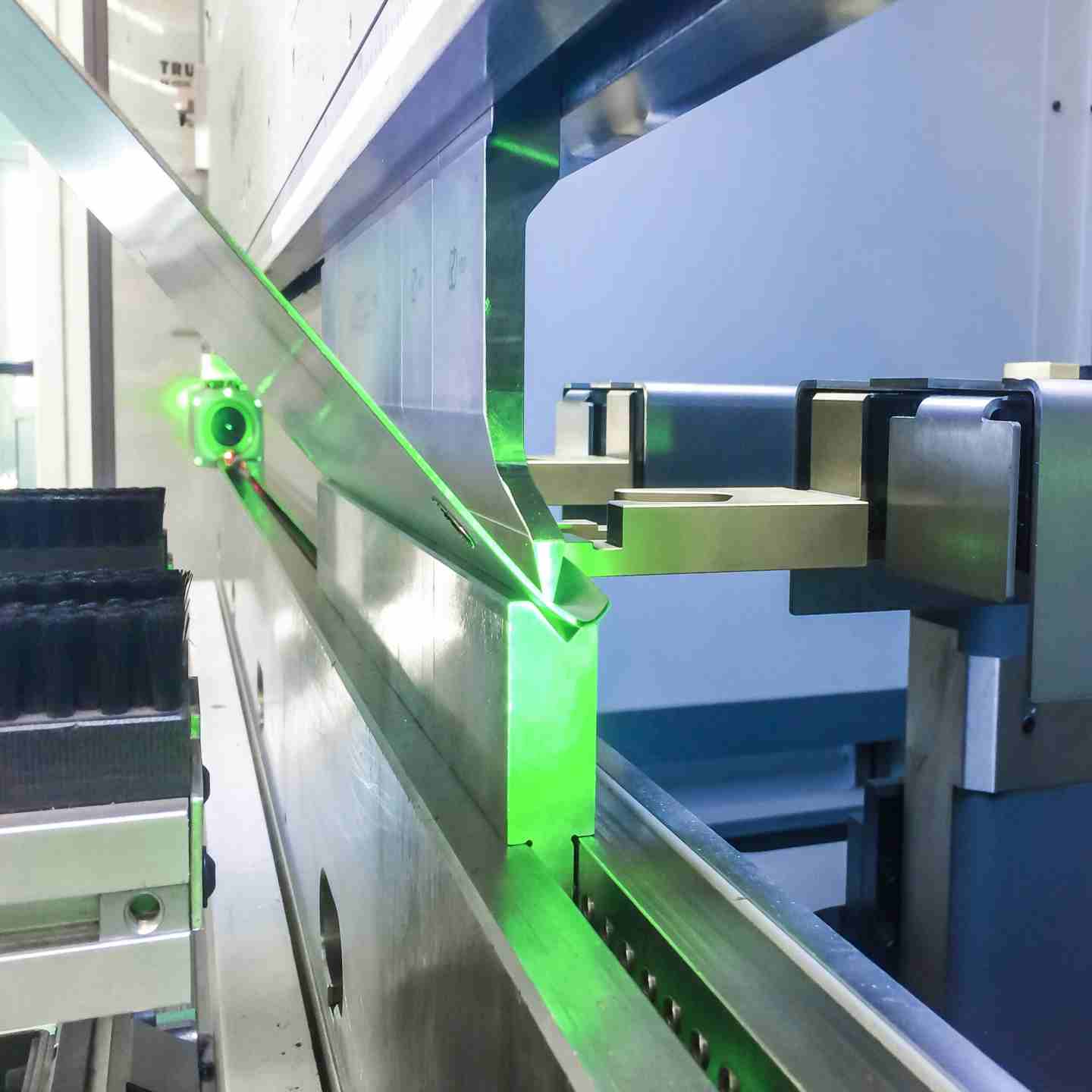
The Lazer Safe Sentinel Plus is a camera based optical guarding system built for press brake retrofit applications, replacing outdated guarding with a solution engineered for both safety and throughput. A laser transmitter and camera receiver mount to the upper beam of the press and create a continuous protection field around the punch tip, letting an operator hold the workpiece as the tool closes while the machine stops automatically if an obstruction is detected. The system is TUV Certified and UL Listed, delivers Category 4 / PLe performance through its SIL 3 rated safety controller, and comes in three configurations: Standard, Automatic (motorized brackets), and XL (extended range for long bed machines).
Key Features
- Achieves Category 4 / PLe performance through a TUV Certified SIL 3 safety controller with encoder feedback
- UL Listed for the USA and Canada; compliant with EN12622, ANSI B11.3-2012, and CSA Z142-10 press brake safety standards
- BendShield optical protection detects obstructions from any angle and stays active until the tool opening reaches 2 mm
- RapidBend Plus technology closes the tool to as little as 2 mm above flat sheet or box profile material, cutting the slow speed travel distance on every cycle
- Maximum recommended optical range of 8 metres (26 feet) on Standard and Automatic configurations, extending to 15 metres (50 feet) on the XL configuration
- Minimum detection resolution of 2 mm with 6 mm object detection capability (Standard/Automatic); 9 mm detection resolution with 14 mm object detection capability on the XL configuration
- Automatic tool scan realigns the protection zone within seconds after a tool change, no manual adjustment required
- AutoSense continuously monitors machine speed, motion, direction, and stopping performance to maintain compliance with overrun and safe speed requirements
- Optional External Device Monitor supports up to four additional devices such as valve sensors or relays, with configurable response time and per device status on the HMI
- Optional monitoring of emergency stop buttons plus side and rear gate interlock switches, with real time status shown on the interface panel
- Dual guarding support lets operators switch between laser protection and a connected third party light curtain from the same HMI, useful for multi height tooling
- Automatic Brackets upgrade (Sentinel Plus Automatic) drives the transmitter and receiver into position with a single HOME/ALIGN button press
Lazer Safe “Sentinel Plus” Press-Brake Guarding System
High-speed, camera-based safeguarding with the Lazer Safe Sentinel Plus
State-of-the-art guard system for press brakes: laser zone, automatic alignment, real-time monitoring and high productivity.
The Lazer Safe Sentinel Plus is a camera based optical guarding system built for press brake retrofit applications, replacing outdated guarding with a solution engineered for both safety and throughput. A laser transmitter and camera receiver mount to the upper beam of the press and create a continuous protection field around the punch tip, letting an operator hold the workpiece as the tool closes while the machine stops automatically if an obstruction is detected. The system is TUV Certified and UL Listed, delivers Category 4 / PLe performance through its SIL 3 rated safety controller, and comes in three configurations: Standard, Automatic (motorized brackets), and XL (extended range for long bed machines).
Key Features
- Achieves Category 4 / PLe performance through a TUV Certified SIL 3 safety controller with encoder feedback
- UL Listed for the USA and Canada; compliant with EN12622, ANSI B11.3-2012, and CSA Z142-10 press brake safety standards
- BendShield optical protection detects obstructions from any angle and stays active until the tool opening reaches 2 mm
- RapidBend Plus technology closes the tool to as little as 2 mm above flat sheet or box profile material, cutting the slow speed travel distance on every cycle
- Maximum recommended optical range of 8 metres (26 feet) on Standard and Automatic configurations, extending to 15 metres (50 feet) on the XL configuration
- Minimum detection resolution of 2 mm with 6 mm object detection capability (Standard/Automatic); 9 mm detection resolution with 14 mm object detection capability on the XL configuration
- Automatic tool scan realigns the protection zone within seconds after a tool change, no manual adjustment required
- AutoSense continuously monitors machine speed, motion, direction, and stopping performance to maintain compliance with overrun and safe speed requirements
- Optional External Device Monitor supports up to four additional devices such as valve sensors or relays, with configurable response time and per device status on the HMI
- Optional monitoring of emergency stop buttons plus side and rear gate interlock switches, with real time status shown on the interface panel
- Dual guarding support lets operators switch between laser protection and a connected third party light curtain from the same HMI, useful for multi height tooling
- Automatic Brackets upgrade (Sentinel Plus Automatic) drives the transmitter and receiver into position with a single HOME/ALIGN button press
Assembly / What's Included
A Sentinel Plus retrofit installation includes the laser transmitter (TX) and camera receiver (RX), mounted on a beam bracket assembly; a sliding or motorized mounting bracket kit, depending on configuration, with rails and bearings for vertical adjustment; the HMI operator panel with color display, cables, and mounting hardware; and full documentation, including an installation manual, alignment guide, and quick reference guide. The press brake's machine controller, any light curtain used for dual guarding, and the wiring that integrates Sentinel Plus with the press control are supplied and configured separately as part of the install. The SIL 3 rated safety controller is built into the transmitter/receiver assembly itself, so no separate safety relay is required for the optical guarding function.
Configuration Options
- Standard: free sliding linear brackets available in 520 mm, 700 mm, or 1000 mm lengths; 8 metre (26 foot) maximum recommended optical range; 2 mm minimum detection resolution and minimum speed change point
- Automatic: motorized brackets available in 550 mm or 700 mm lengths with HOME/ALIGN controls for tool change automation; 6 metre (20 foot) maximum recommended optical range when using Automatic Brackets
- XL: extended range up to 15 metres (50 feet) for long bed machines; 9 mm minimum detection resolution, 14 mm object detection capability, and 14 mm minimum speed change point; standard linear brackets available in 700 mm or 1000 mm lengths
Monitoring & Interface Options
- Connector types: M12 connector (12 pin) for the transmitter and receiver; M12 connector (8 pin) for the HMI panel
- AutoSense automatic monitoring of control commands, motion, direction, speed, and stopping performance
- Optional External Device Monitor for up to four devices, with configurable response time
- Optional monitoring of emergency stop buttons and side/rear gate interlock switches
- Dual guarding support for integrating a third party light curtain, managed through the same HMI
Environmental Ratings
Not specified in the manufacturer materials reviewed for this draft. See the note in Questions & Assumptions below.
Applicable Safety Standards
Standards to be confirmed by PowerSafe. See: Sentinel Plus Operation Manual (Lazer Safe, document LS-CS-M-073), Certification and Standards Compliance section.
Optical Detection & Alignment Issues
Machine won't run, false trips, or inconsistent detection
- Confirm the transmitter and receiver are correctly aligned and unobstructed
- Check the status LEDs on the transmitter (power/laser) and receiver (power/sensors/automatic alignment) for fault indication
- Inspect the lens surfaces on both transmitter and receiver for dust, coolant residue, or debris
- Verify the mounting brackets are sliding freely and haven't shifted out of position
- Confirm the correct tool has been scanned after a tool change
Tool Scan & Calibration Issues
Protection zone doesn't match the installed tool
- Rerun the automatic tool scan by pressing the TOOL SCAN button on the receiver after any tool change
- Confirm Special Tools Mode is selected for nonstandard tool profiles
- Check that the tool tip is fully visible to the camera receiver during the scan
- Verify no obstruction is blocking the receiver's view of the punch during calibration
HMI & Status Display Issues
Panel shows an error, blank screen, or unclear machine state
- Check the connector and cable between the HMI panel and the controller
- Confirm the panel's magnetic mount hasn't come loose or moved out of the operator's view
- Reference the onscreen instructions and messages, which indicate the specific fault or required action
- Power cycle the system if the display becomes unresponsive, then confirm normal status returns
AutoSense & Machine Monitoring Faults
Speed or stop time fault reported
- Confirm AutoSense settings match the press brake's actual motion and control characteristics
- Check for mechanical wear or drift in stopping performance
- Verify encoder feedback wiring on the safety controller is intact
- Review recent AutoSense fault history on the HMI for repeat patterns
External Device Monitor Faults
Connected device shows a fault or is not recognized
- Confirm wiring to each monitored device (valve sensor, relay, etc.) is intact and correctly terminated
- Check the configured response time against the connected device's actual response
- Verify the device status shown on the HMI matches the device's physical state
- Test each of the four EDM channels individually to isolate the fault
Mounting Bracket Issues
Brackets won't slide, won't return to position, or Automatic Brackets don't respond
- For Standard or manual brackets, confirm rails and bearings are clean and move freely
- For Automatic Brackets, check the motorized drive system and confirm HOME/ALIGN commands are being received
- Verify the Automatic Brackets' manual directional controls work in the event of a power failure
- Inspect for physical damage from contact during free sliding operation
Dual Guarding & Light Curtain Integration Issues
System won't switch modes or light curtain status is unclear
- Confirm the correct guarding mode is selected on the HMI (laser or light curtain)
- Check wiring between Sentinel Plus and the connected third party light curtain
- Verify mute point setup is correctly configured for the active guarding mode
- Confirm automatic speed monitoring is active for the selected mode
Environmental Factors
Degraded or inconsistent performance over time
- Check for dust, oil, or debris accumulation on the transmitter and receiver
- Clean optical surfaces on the manufacturer's recommended schedule
- Inspect for excessive vibration affecting alignment, especially on long bed machines using the XL configuration
- Confirm ambient conditions remain within the system's rated operating range (consult the Operation Manual for exact limits)
Preventive Maintenance
To avoid recurring issues:
- Inspect and clean transmitter and receiver optics on a regular schedule
- Check mounting bracket rails, bearings, and hardware for wear or looseness
- Verify tool scan accuracy after every tool change
- Confirm EDM and AutoSense settings remain correctly configured after any machine control changes
Fault Tracking & Continuous Improvement
- Log every fault or stop event, including date, tool in use, and status LEDs at the time
- Look for recurring patterns, such as repeated alignment faults tied to a specific tool or shift
- Use fault history data to identify root causes and adjust maintenance intervals accordingly