
(Two Layout Options for Risk-Reduced, Flexible Perimeter Protection)
When protecting a CNC router without full perimeter hard guarding, radar-based safety detection can provide a flexible and robust alternative — especially in applications where material loading, sheet handling, or large part envelopes make fencing impractical.

Below is a practical guide outlining two layout concepts using Inxpect safety radars for a CNC router. These are solution options, not final engineered designs. Final placement must be validated through a formal risk assessment and safety distance calculation.
Option 1: Ground-Mounted S201A-W Sensors Around the Machine Base
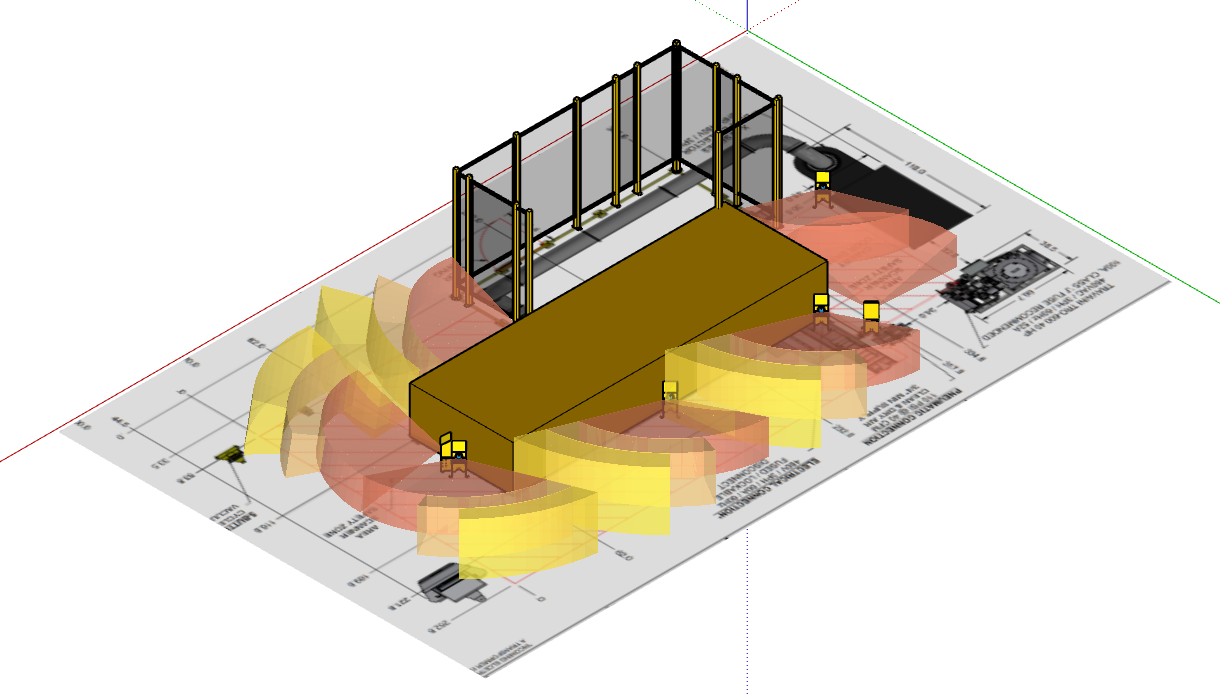
Concept: Use multiple Inxpect S201A-W sensors mounted low around the base of the CNC router to create a rectangular detection perimeter approximating the safety zone shown in the drawing.
Configuration Summary
- (5) S201A-W sensors
- Mounted near ground level.
- Positioned along:
- Front of machine
- Both sides
- Multiple detection fields per sensor configured to approximate rectangular safety footprint.
Advantages
- Lower overall cost
- Fewer sensor models required.
- Reduced installation complexity
- Minimal structural additions (no fencing required)
This approach uses each sensor’s configurable detection fields to create a layered perimeter.
Critical Design Considerations
Detection Field Geometry
The S201A-W uses “sawtooth” detection fields — not a perfectly straight edge.
That means:
- The edge of detection is not razor clean.
- Minor motion near the edge may result in nuisance trips.
- A buffer zone should be maintained between:
- Detection edge
- Operator panels
- Floor pedestals
- High-traffic zones
In your layout, the detection footprint slightly exceeds the ~60-inch width shown in the drawing.
This may actually be beneficial once you calculate:
Safety Distance = (K × T) + C
Where:
- K = approach speed constant
- T = total stopping time (machine stop + detection delay)
- C = reach-over/reach-through factor
The extended width may be necessary after applying safety distance calculations.
Nuisance Trip Risk
Although the S201A-W is highly resistant to environmental noise, this layout is closer to machine motion.
Areas of concern:
- Moving gantry
- Spindle carriage
- Energy chains
- Cable carriers
- Operator movement
This layout is robust against equipment motion — but edge zones must be respected.
Operator Interface Placement
The following may require repositioning:
- Operator control panel
- 5-button floor pedestal
They should be placed:
- Outside detection fields
- Or with adequate separation from sawtooth edges
If not adjusted, nuisance resets may occur.
When Option 1 Makes Sense
- Budget-sensitive retrofit
- Limited installation time
- Minimal structural changes allowed.
- Controlled access points
Option 2: Hybrid System (S202A-MS for Access + S201A-W for Restart Prevention)
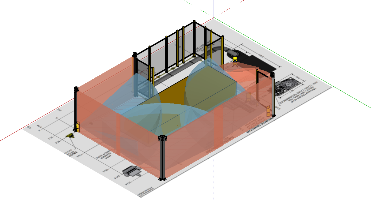
Concept: Use Inxpect S202A-MS sensors for primary access detection, and Inxpect S201A-W sensors inside the area for restart prevention only.
This mirrors the more robust strategy used in prior industrial implementations.
Configuration Summary
- (5) S202A-MS sensors
- Thin profile
- Positioned for access detection.
- (3) S201A-W sensors
- Interior coverage
- Restart prevention only.
- Muted during normal machine operation.
- Short fence segment added on one side.
Why This Layout Is More Robust
Cleaner Access Boundary
The S202A-MS provides:
- More defined detection boundaries
- Higher immunity to nuisance motion
- Thin physical profile
- Better zone control for access detection
This allows the safety zone to match the drawing footprint more closely.
Interior “Blanket” for Restart Prevention
The S201A-W sensors inside the zone:
- Prevent restart if someone remains inside.
- Are muted during operation.
- Reactivate during stop/reset cycle.
This dual-layer approach separates:
- Access detection
- Presence detection
That separation increases stability and reduces nuisance trips.
Energy Chain Consideration
The CNC router’s cable chain is likely to trip the S202A-MS on the side.
Mitigation used in layout:
- Pushed detection field further from machine table.
- Added short fencing section.
- Created physical barrier between motion and sensor.
This is an important real-world integration detail.
Comparison Summary
| Feature | Option 1: All S201A-W | Option 2: Hybrid Layout |
| Cost | Lower | Higher |
| Installation Complexity | Simpler | Moderate |
| Nuisance Resistance | Moderate | High |
| Footprint Accuracy | Approximate | Closer match |
| Restart Prevention | Integrated | Dedicated interior layer |
| Motion Immunity | Good | Better |
Engineering Checklist Before Finalizing Design
Regardless of option:
1. Perform Formal Risk Assessment
- Task-based risk assessment (TBRA)
- Validate hazard severity and frequency.
- Confirm Performance Level (PL) required.
2. Calculate Safety Distance
- Total stop time measurement
- Include:
- Radar reaction time
- PLC safety logic delay
- Output contactor delay.
- Add reach-over and reach-through compensation.
3. Validate Control Architecture
- Safety relay vs safety PLC
- PLd/PLe determination
- Category 3 or 4 confirmation
- Muting logic validation (for Option 2)
4. Consider Environmental Factors
- Nearby forklift traffic
- Material carts
- Stacked sheet goods.
- Overhead cranes
Practical Recommendation
If the CNC router:
- Has significant operator interaction?
- Has high gantry movement?
- Has cable chain motion near edges?
The hybrid S202A-MS + S201A-W layout will produce fewer nuisance trips and higher long-term stability.
If the machine:
- Is in a low-traffic area.
- Has limited edge motion.
- Requires a lower cost retrofit.
The all S201A-W layout may be sufficient.
Final Thought

Radar-based safety systems for CNC routers offer flexibility that light curtains and fencing sometimes cannot — especially for large-format tables and frequent material handling.
However, the difference between a stable system and a frustrating one comes down to:
- Field geometry
- Buffer spacing
- Stop time validation.
- Real-world motion behavior
- Proper separation of access vs restart functions


